Do you have a question about the Eurotherm 2132 and is the answer not in the manual?
Details the physical dimensions and installation requirements for the PID controllers.
Step-by-step guide for installing the PID temperature controller into a panel.
Instructions on how to safely disconnect the controller from its sleeve.
Specifies the minimum clearance required between controllers for proper operation.
Information on the acceptable wire sizes for terminal connections and tightening torque.
Illustrates the standard wiring configuration for the PID temperature controller.
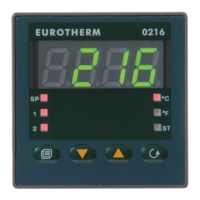
Guide on how to modify the target temperature (setpoint) for the controller.
How to check and change the temperature display units (°C, °F, K).
Procedure for acknowledging active alarms on the controller.
Explains the various alarm messages displayed by the controller and their meanings.
How to monitor the current heating or cooling demand of the controller.
Instructions on navigating and modifying controller parameters.
Guide to setting the specific trip points for different alarm conditions.
Overview of the different parameter lists available for configuration.
A brief summary of how to navigate and use the parameter lists.
Detailed tables outlining controller parameters, ranges, and default settings.
Instructions for managing parameter visibility and access levels.
Guide on promoting parameters to the HOME display for quick access.
Steps to revert from configuration or edit modes back to operator level.
Instructions on how to configure and operate the built-in timer function.
Details Timer Mode 1: dwell time followed by switching off.
Details Timer Mode 2: dwell time without switching off after timing.
Details Timer Mode 3: timing from cold, then switch off.
Details Timer Mode 4: timing from cold without switch off.
Details Timer Mode 5: delayed activation after timing.
How to program a ramp-dwell profile using timer and rate limit settings.
Procedures for initiating and resetting the controller's timer.
Guide on accessing different configuration levels of the controller.
Settings related to display units, decimal places, and control type.
Details on configuring sensor input types, scaling, and compensation.
How to set up and configure the internal soft alarms.
Configuration of relay and logic outputs for various functions.
Associating relay or logic outputs with alarms or digital functions.
How to assign multiple alarms or functions to a single output.
Procedure to remove all alarms or functions from a specific output.
Information on setting and managing access passwords for configuration.
Steps to exit the configuration mode and return to operator level.
Explains diagnostic messages and their meanings for troubleshooting.
Setting cycle times for heating and cooling outputs before tuning.
Step-by-step guide for performing automatic PID tuning.
Visual representation of the automatic tuning process oscillation.
How cutback values are determined during automatic tuning.
Manually adjusting cutback parameters for overshoot/undershoot control.
Using manual reset to remove steady-state errors.
Instructions for unpacking, storing, and handling the controller upon receipt.
Precautions to prevent damage from electrostatic discharge when handling the unit.
Guidelines for cleaning the controller's exterior and labels.
Explanation of safety symbols used on the controller.
Requirements for qualified personnel performing installation.
Safety requirement to enclose live parts of the controller.
Guidelines for proper wiring of the controller according to regulations.
Requirements for installing a power isolating switch or circuit breaker.
Specifies the maximum continuous voltage ratings for the controller terminals.
Precautions regarding conductive pollution in the mounting environment.
Importance of over-temperature protection in control system design.
Guidance for meeting Electromagnetic Compatibility requirements.
Best practices for routing wires to minimize electrical noise interference.
| Control Type | PID |
|---|---|
| Display | LED |
| Control Algorithm | PID, On/Off |
| Input Type | Thermocouple, RTD |
| Output Type | Relay |
| Dimensions | 48 x 48 mm |
| Communication | RS485 |
| Operating Temperature | 0 to 55°C |
| Supply Voltage | 100 to 240 VAC, 24 VAC/DC |