Do you have a question about the Eurotherm 2208e and is the answer not in the manual?
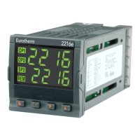
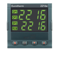
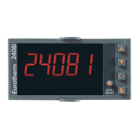
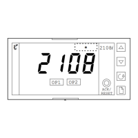
Overview of the controller's front panel buttons and display indicators.
Basic principles of operation and initial setup of the controller.
Explanation of how to access and navigate parameter lists.
How to switch between automatic and manual operating modes.
A brief overview of how to navigate and change parameters.
Procedure for selecting between primary and secondary setpoints.
Configuration and operation of ramp/dwell programs.
Visual representation of parameter organization within the controller.
Diagram illustrating parameter navigation flow for Part A.
Detailed listing of controller parameters, default values, and ranges.
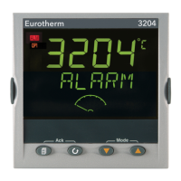
Definition and types of alarms used in the controller.
How alarms can activate specific output relays.
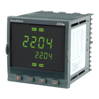
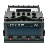
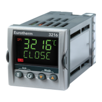
Identification of physical components and features of the controller.
Overview of controller features, modular construction, and ports.
Instructions for physically installing the controller into a panel.
General information and warnings regarding controller wiring procedures.
Explanation of Proprietary Data System (PDS) operating modes.
Information on using snubbers for inductive loads with relay/triac outputs.
Illustrative wiring diagram for a single control loop.
Wiring details for serial communication interfaces.
Wiring instructions for DeviceNet communication option.
Explanation of the various user access levels and their capabilities.
Procedure for logging into different access levels using passwords.
How to configure parameter visibility and alterability for operator level.
Explanation of the purpose and goals of controller tuning.
Method for automatically determining optimal PID tuning parameters.
Step-by-step guide on performing manual and automatic tuning.
Procedures for manually adjusting PID parameters using Ziegler-Nichols method.
Steps to enter the controller's configuration mode.
How to navigate and select parameters within configuration.
Procedure for exiting the configuration mode safely.
General overview of the controller configuration process.
Diagram illustrating parameter organization for configuration Part A.
Detailed tables of configurable parameters and their settings.
Setup for ModBus, EI-Bisynch, and DeviceNet communications.
Specifics related to the DeviceNet communication option.
Explains why and when to perform user calibration.
How to enable user calibration in configuration mode.
Procedure for calibrating the controller at one point.
Method for calibrating the controller at two distinct points.
Viewing calibration points and offset values.
Understanding the concepts of alarms and events in the controller.
How digital outputs can be used for alarms or events.
Steps to configure soft alarms for indication only.
Linking configured alarms to physical output relays.
Combining multiple alarms to trigger a single output.
Procedure to detach alarms from an output.
Overview of parameters specific to motorized valve control.
Steps to set up and commission the motorized valve controller.
Applications and setup tables for motorized valve control.
Introduction to monitoring and diagnosing load current.
Wiring diagram for load current monitoring modes 1 and 2.
Wiring diagram for load current monitoring mode 5.
How to operate and read load current and display modes.
Procedure for setting alarm trip levels for load current.
Information on using relay outputs for alarms.
Steps to configure PDS load current diagnostics.
Setting up low and high current trip alarms.
Linking soft alarms to a relay output.
Adjusting the scaling factor for current readings.
Explanation of the controller's retransmission capabilities.
Steps to configure analogue output signals for retransmission.
How to scale retransmitted output signals for different ranges.
| Control Type | PID |
|---|---|
| Operating Temperature | 0 to 55°C |
| Input Types | Thermocouple, RTD |
| Output Types | Relay, SSR |
| Display | LED |
| Supply Voltage | 100 to 240 VAC |
| Communication | RS485 |