Do you have a question about the Eurotherm 2408i and is the answer not in the manual?
Lists all items included in the product package.
Details physical dimensions and procedures for mounting the indicator.
Explains changes in the sleeve design and installation impact.
Guides on wiring and connecting modules and power.
How to check and change temperature or process value units.
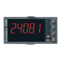
Customizes the main display screen (front and back).
Configuration and management of process and diagnostic alarms.
Procedure for setting a zero offset for weighing applications.
Navigational overview for accessing and modifying parameters.
Lists and explains various configurable parameters.
Defines different user access levels and their default codes.
Visual guide to parameter access in full and edit modes.
Detailed lists of parameters for various functions.
Customizing operator display by managing parameter visibility.
Explains different calibration methods for inputs and outputs.
Details on installing and connecting optional plug-in modules.
Setting up indicator parameters defining its operation.
Illustrates parameter locations within the indicator's functional blocks.
Shows the flow for accessing configuration parameters.
Lists parameters for fixed indicator functions.
Lists parameters for various plug-in modules.
General compliance, unpacking, cleaning, safety symbols, and ESD precautions.
Guidance on charged capacitors, live sensors, wiring, power isolation, voltage, and pollution.
EMC compliance requirements and advice on wire routing.
| supply voltage | 100 to 240Vac -15%+10% OR 24 Vdc or ac 15%+20% |
|---|---|
| power consumption | 15W max |
| transmitter supply rating | 20mA, 24Vdc |
| operating ambient temperature | 0 to 55oC |
|---|---|
| operating ambient humidity | 5 to 95% RH non-condensing |
| storage temperature | -10 to +70oC |
| low level range | -100 to +100mV |
|---|---|
| high level range | 0-20mA or 0-10Vdc |
| input impedance for mV inputs | >10MΩ |
| digital inputs switching voltage/current | 24Vdc/20mA nominal |
|---|---|
| relay rating | 2A, 264Vac resistive |
| triple logic output | 8mA, 12Vdc per channel |
| number of alarms | Four |
|---|---|
| alarm delay | OFF to 999.9 secs |
| alarm types | High, low, deviation high, deviation low, deviation band, rate of change in units/sec, rate of change in units/min, new alarm status |
| dimensions | 96W x 48H x 150D |
|---|---|
| weight | 400g max |
| panel sealing | IP65 |