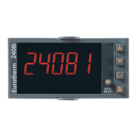
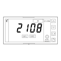
2408
i
Indicator and Alarm Unit
1 User Guide
Thank you for choosing the 2408i panel mounted indicator. It will provide accurate measurement and display of
temperature and other process variables. A modular build accepts a wide range of plug-in modules allowing: up
to four alarm outputs, two process variable (PV) inputs, direct strain gauge/pressure sensor measurements, custom
linearisation, analogue retransmission, remote setpoint (SP) input and digital communications.
The indicator is supplied configured in accordance with the order code. The order code and instrument serial
number is shown on a label fixed to the top of the case, and this can be checked against the order code given in
section 3 of these instructions.
1.1 CONTENTS OF PACKAGE
1. A peel-off label set - a convenient position is to fix a label to the top right of
the display.
2. A 2.49Ω resistor used as the load resistor for mA inputs
3. Two panel retaining clips
1.2 DIMENSIONS AND INSTALLATION
1.2.1 To Install the Indicator
Please read the safety information in section 4 before proceeding.
The indicator is intended to be mounted on a panel within an enclosure such as a control cubicle.
1. Prepare the panel cut-out to the size shown.
2. Insert the indicator through the cut-out.
3. Spring the panel retaining clips into place. Secure the indicator in position by holding it level and pushing both retaining clips forward.
4. Peel off the plastic film protecting the front of the indicator.
1.2.2 Removing The Indicator From The Sleeve
The indicator can be removed from its sleeve by easing the latching ears outwards and pulling it
forward out of the sleeve. When plugging the indicator back into its sleeve, ensure that the
latching ears click into place to maintain the moisture sealing protection.
This indicator meets the European directives on safety and EMC
,
96 mm (3.78 in)
Panel cut-out
92 X 45 mm
-0.0 +0.8
-0.0 +0.6
3.62 X 1.77 in
0.0 +0.03
-0.0 +0.02
Latching ears (top & bottom)
48 mm
(1.89 in)
E
U
R
O
T
H
E
R
M
ACK/
RESET
2408
I
AL2
AL1 AL3
AL4
Panel retaining clips
150mm (4.01in)
Recommended minimum
spacing of indicators
(Not to scale)
38mm (1.5in)
38mm (1.5in)
o
C
o
F K kPa V mV
m/s cm/s l/h mWG A mA
x10 1x10 l/min T/h % %RH
p.s.i bar mbar mPas %pH pH
p.s.i.x1
0
mmHg Kg/cm
2
gal/min rev/min mile/h
Amps
ENG
!