EasyManua.ls Logo

Eurotherm 2216e User Manual

Eurotherm 2216e
120 pages
To Next Page IconTo Next Page
Page #1 background imageLoading...
Page #1 background image
Installation and Operation Handbook Contents
2216e Controller Handbook Part No. HA026639 Issue 2.0 Oct -00 a-1
MODEL 2216e
TEMPERATURE CONTROLLER
INSTALLATION AND OPERATION HANDBOOK
Contents Page
Chapter 1 OPERATION 1-1
1.1 FRONT PANEL LAYOUT ................................................................1-2
1.2 GETTING STARTED .......................................................................1-4
1.2.1 Viewing The Process Value and Setpoint............................................1-4
1.2.2 To Adjust The Setpoint ........................................................................1-4
1.2.3 Viewing The Display Units ...................................................................1-5
1.2.4 Use Of The “SCROLL” Button
.......................................................1-5
1.2.5 Use Of The ‘PAGE’ Button
.............................................................1-6
PARAMETER LISTS .................................................................................1-7
1.4 MANUAL OR AUTOMATIC CONTROL..........................................1-8
1.4.1 Selecting Auto/Manual Operation........................................................1-8
1.4.2 How To Manually Adjust Output Power ...............................................1-9
1.5 SUMMARY.......................................................................................1-9
1.6 SETPOINT 1 OR SETPOINT 2......................................................1-10
1.6.1 To Select Setpoint 1 or Setpoint 2.....................................................1-10
1.7 RAMP DWELL FUNCTION ...........................................................1-11
1.7.1 To Set up a Ramp/Time Program......................................................1-11
1.7.2 To Run the Program ..........................................................................1-12
1.7.3 Power Failure During Program Run...................................................1-12
1.8 LOCATION OF PARAMETERS - BLOCK DIAGRAM ..................1-13
1.9 NAVIGATION DIAGRAM
(Part A)
..................................................1-14
NAViGATION Diagram
(Part B)
..............................................................1-15
1.10 PARAMETER TABLES ..............................................................1-16
1.10.1 HOME Display................................................................................1-16
1.10.2 Alarm List .......................................................................................1-17
1.10.3 Autotune List ..................................................................................1-17
1.10.4 PID List...........................................................................................1-18
1.10.5 Setpoint List ...................................................................................1-19
1.10.6 Input List.........................................................................................1-20
1.10.7 On/Off List......................................................................................1-20
1.10.8 Output List......................................................................................1-21
1.10.9 Communications List......................................................................1-21
1.10.10 Access List.....................................................................................1-21

Table of Contents

Other manuals for Eurotherm 2216e

Question and Answer IconNeed help?

Do you have a question about the Eurotherm 2216e and is the answer not in the manual?

Eurotherm 2216e Specifications

General IconGeneral
Control TypePID
Input TypesThermocouple, RTD, DC Linear
MountingPanel Mount
Output TypesRelay
DisplayLED
Supply Voltage100 to 240 VAC
Dimensions48 x 48 mm
CommunicationRS485

Summary

Chapter 1 OPERATION

1.1 FRONT PANEL LAYOUT

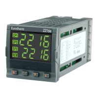
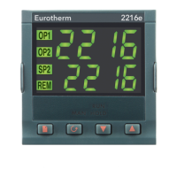
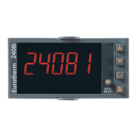
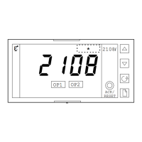
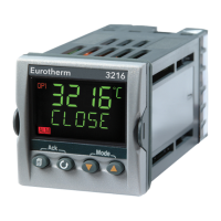
Explains the physical layout of the controller's front panel and its components.

1.2 GETTING STARTED

Provides initial steps for using the 2216e controller, including basic operation.

1.3 PARAMETER LISTS

Introduces the concept of parameter lists for controller settings and configuration.

1.4 MANUAL OR AUTOMATIC CONTROL

Details the controller's automatic and manual operating modes for output control.

1.5 SUMMARY

Provides a concise summary of the topics covered in the chapter.

1.6 SETPOINT 1 OR SETPOINT 2

Explains the process of selecting between two available setpoints on the controller.

1.7 RAMP DWELL FUNCTION

Details the setup and operation of the ramp dwell function for timed programs.

1.8 LOCATION OF PARAMETERS - BLOCK DIAGRAM

Illustrates the controller's internal structure and parameter locations via a block diagram.

1.9 NAVIGATION DIAGRAM (Part A)

Provides a visual guide for navigating through the controller's menus and parameters.

1.10 PARAMETER TABLES

Lists and describes all available parameters for the controller in a tabular format.

1.11 ALARMS

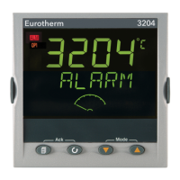
Explains the functionality and types of alarms used in the 2200e series controllers.

1.12 ALARM RELAY OUTPUT

Details how alarm conditions can trigger or operate the controller's relay outputs.

Chapter 2 INSTALLATION

2.1 INSTRUMENT LAYOUT

Describes the physical layout and components of the 2216e controller instrument.

2.2 INTRODUCTION

Provides a general introduction to the Model 2216e controller's features.

2.3 MECHANICAL INSTALLATION

Covers the physical steps and requirements for installing the controller.

2.4 WIRING

Explains the electrical wiring procedures and considerations for the controller.

2.5 PDS MODES

Describes the proprietary Data Server (PDS) modes for controller communication.

2.6 SNUBBERS

Details the use and function of snubber components for output protection.

2.7 TYPICAL SINGLE LOOP WIRING DIAGRAM

Presents a typical wiring diagram for a single loop configuration of the controller.

2.8 COMMUNICATION CONNECTIONS

Explains the different types of communication connections supported by the controller.

2.9 DEVICENET WIRING TO SERIES 2200E CONTROLLERS

Details the wiring procedures for connecting the controller to a DeviceNet network.

Chapter 4 TUNING

4.1. WHAT IS TUNING?

Explains the fundamental concept and purpose of tuning a control system.

4.2. AUTOMATIC TUNING

Describes the automatic tuning process and how the controller determines optimal parameters.

4.3. HOW TO TUNE

Provides step-by-step instructions on how to perform the tuning procedure.

4.4. MANUAL TUNING

Outlines the method for manually adjusting controller tuning parameters.

Chapter 5 CONFIGURATION

5.1 SELECTING CONFIGURATION LEVEL

Details the procedure for accessing and selecting the controller's configuration level.

5.2 SELECTING A CONFIGURATION PARAMETER

Explains how to navigate and select specific parameters within the configuration menu.

5.3 LEAVING CONFIGURATION LEVEL

Describes the steps required to exit the controller's configuration level safely.

5.4 STEPS INVOLVED IN CONFIGURING A CONTROLLER

Outlines the general steps involved in configuring the controller for operation.

5.5 NAVIGATION DIAGRAM (PART A)

Provides a visual diagram illustrating navigation through configuration menus (Part A).

5.6 NAVIGATION DIAGRAM (PART B)

Provides a visual diagram illustrating navigation through configuration menus (Part B).

5.7 CONFIGURATION PARAMETER TABLES

Presents detailed tables of all configurable parameters and their settings.

5.8 CONFIGURATION OF DIGITAL COMMUNICATIONS

Details the configuration process for the controller's digital communication modules.

5.9 DEVICENET

Provides specific instructions for configuring DeviceNet communication for the controller.

Chapter 6 USER CALIBRATION

6.8 WHAT IS THE PURPOSE OF USER CALIBRATION?

Explains the reasons and benefits of performing user calibration on the controller.

6.9 USER CALIBRATION ENABLE

Details how to enable the user calibration feature in the controller's configuration.

6.10 SINGLE POINT CALIBRATION

Guides through the process of performing a single-point calibration for offset adjustment.

6.11 TWO POINT CALIBRATION

Explains the procedure for calibrating the controller at two distinct points.

6.12 CALIBRATION POINTS AND CALIBRATION OFFSETS

Describes the recorded calibration points and the applied offsets.

Chapter 7 ALARM CONFIGURATION

7.1 DEFINITION OF ALARMS AND EVENTS

Defines alarms and events, explaining their purpose and types within the controller.

7.2 DIGITAL OUTPUT FUNCTIONS

Details the available digital output functions that can be configured as alarms or events.

7.3 STEP1 - CONFIGURING THE FOUR ‘SOFT’ ALARMS

Outlines the first step in configuring the controller's 'soft' (indication-only) alarms.

7.4 STEP 2 - ATTACHING AN ALARM TO A PHYSICAL OUTPUT

Explains the process of linking configured alarms to physical output relays.

7.5 STEP 3 - GROUPING ALARMS ON A SINGLE OUTPUT

Details how to group multiple alarms to trigger a single output relay.

7.6 STEP 4 - REMOVING ALARMS FROM AN OUTPUT

Describes how to detach or remove alarms from an assigned output relay.

Chapter 8 MOTORUSED VALVE CONTROL

8.1. PARAMETERS FOR MOTORISED VALVE CONTROL

Lists and describes parameters specific to motorized valve control configuration.

8.2. COMMISSIONING THE MOTORISED VALVE CONTROLLER

Provides steps for commissioning the controller when used for motorized valve control.

8.3. MOTORISED VALVE APPLICATIONS

Discusses various applications and use cases for the motorized valve control feature.

Chapter 9 LOAD CURRENT MONITORING & DIAGNOSTICS

9.1 LOAD CURRENT MONITORING AND DIAGNOSTICS

Introduces load current monitoring and diagnostic capabilities of the controller.

9.2 EXAMPLE WIRING DIAGRAM (MODE 1 & 2 OPERATION)

Shows an example wiring diagram for load current monitoring in modes 1 and 2.

9.3 OPERATION

Explains the operational procedures for using the load current monitoring features.

9.4 TO SET THE ALARM TRIP LEVELS

Details how to set trip levels for load current alarms.

9.5 RELAY OUTPUTS

Explains the use of relay outputs for alarms and other purposes.

9.6 TO CONFIGURE PDS LOAD CURRENT DIAGNOSTICS

Guides on configuring PDS load current diagnostics for the controller.

Chapter 10 RETRANSMISSION

10.1 WHAT IS RETRANSMISSION

Defines retransmission and explains its purpose in generating analogue output signals.

10.2 TO CONFIGURE RETRANSMISSION

Provides instructions for configuring the retransmission function of the controller.

10.3 SCALING RETRANSMITTED OUTPUT SIGNALS

Explains how to scale the analogue output signals for retransmission.

Appendix A UNDERSTANDING THE ORDERING CODE

Appendix B SAFETY and EMC INFORMATION

Related product manuals