To Remove the Controller
from its Sleeve
Ease the latching ears outwards and pull
the controller forward.
When plugging back in ensure that the
latching ears click into place to maintain
the IP65 sealing.
Pour retirer le régulateur de son
manchon
Le régulateur peut être sorti de son manchon, par
traction vers l'avant après déblocage des clips de
verrouillage .
Au remontage dans son manchon, s'assurer que
les clips s’enclenchent correctement, afin que le
niveau de protection IP65 soit maintenu.
Reglerwechsel
Durch Auseinanderziehen der
Außenklammern
und nach vorne ziehen
des Reglers können Sie das Gerät aus dem
Gehäuse entnehmen.
Wenn Sie das Gerät zurück in das Gehäuse
stecken, versichern Sie sich, dass die
Außenklammern einrasten.
Wiring
Check the Order Code printed on the
label on the controller sleeve against
that given below to ensure that the
product is supplied and configured
correctly for your application.
Please read Safety and EMC Information
before proceeding.
Wire Sizes
The screw terminals accept wire sizes from
0.5 to 1.5 mm (16 to 22AWG). Hinged
covers prevent hands or metal making
accidental contact with live wires. The rear
terminal screws should be tightened to
0.4Nm (3.5lb in).
Cablage
Les étiquettes situées sur les côtés du
régulateur portent le code de commande,
le numéro de série et les branchements.
Vérifiez ces informations pour garantir
que le produit livré est correctement
configuré pour votre application.
Prière de lire les consignes de sécurité
avant toute utilisation.
Diamètres de fil
Les borniers à vis acceptent les fils de 0,5 à
1,5 mm (16 à 22AWG). Les capots articulés
évitent tout contact accidentel avec les fils
sous tension. Les vis des borniers arrière sont
à serrer à 0,4 Nm.
Verdrahtung
Der Geräteaufkleber auf der Seite des Reglers
informiert Sie über Bestellcode, Seriennummer
und Verdrahtung.
Überprüfen Sie diese, um sicherzustellen, dass das
Produkt für Ihre Anwendung korrekt konfiguriert
ist.
Bitte lesen Sie vor Einbau des Reglers die
Sicherheitsinformationen
Kabelquerschnitt
Die Schraubklemmen auf der Regler Rückseite sind
für Kabelquerschnitte von 0,5 bis 1,5 mm
2
vorgesehen (16 bis 22AWG). Die Klemmenleisten
sind jeweils mit einer Kunststoffabdeckung zum
Schutz vor Berührung versehen. Achten Sie beim
Anziehen der Schrauben darauf, dass das
Drehmoment 0,4 Nm nicht überschritten wird.
Configuration Code Code Logiciel Konfigurations-Code
1. Sensor
Input
Entrée
capteur
Sensortyp
Thermocouple, Thermoelement
K, J, T, L, N, R, S, B, P (Platinel II)
RTD
Z PT100
Custom thermocouple
C *C W5%Re/W26%Re (Hoskins)
D W3%Re/W25%Re
E E
1 Ni/Ni18%Mo
2 Pt20%Rh/Pt40%Rh
3 W/W26%Re (Englehard)
4 W/W26%Re (Hoskins)
5 W5%Re/W26%Re (Englehard)
6 W5%Re/W26%Re (Bucose)
7 Pt10%Rh/Pt40%Rh
8 Exergen K80 IR pyrometer
Process, Prozess
M -9.99 to +80.00m
0 to 10Vdc
,
4. Units Unités Anzeigeeinheiten
C Celsius F Fahrenheit K Kelvin
X None (Linear) Néant
(Linéaire)
Keine (Linear)
2 & 3. Range min/max Plage Bereich
Examples -210 1200 -210
O
C 1200
O
C
Exemples -340 2192 -340
O
F 2192
O
F
Beispiele
7. Options Options Optionen
Control action Régulation Regelaktion
XX PID
Reverse
(standard)
PID Inverse PID Reverse
DP PID Direct PID Directe PID Direk
Power
feedback,
Compensation
variations
secteur
Leistungs-
rückführung
XX Enabled -
logic, relay
& triac
heating
outputs
Activé Aktiviert
Logik, Relais &
Triak
Heizausgänge
PD Disabled Invalidée Inaktiv
Cooling Refroidissemen
Kühlen
XX Linear Linéair Linear
CF Fan Refroid. par
ventilateur
Luftkühlung
CW Water Refroid. par eau Wasser-
kühlung
CL Oil Refroid. par huile Ölkühlung
1 2 3 4 5 6 7
5 & 6.
Digital input 1/2 Entrée
Logique 1/2
Digital
Eingänge 1/2
XX None Néant Kein Ausgang
AM Manual Manuel Manuell
SR Remote SP Consigne
Externe
Sollwertrampe
S2 Second SP Deuxième
consigne
Zweiter
sollwert
EH Integral hold Blocage de
l’intégrale
Integral hold
AC Alarm ack Acquittement
alarme
Alarm-
quitterung
SB Standby Standby Standby
M5 CTX mode 5 CTX mode 5 CTX Modus 5
Pièces Fournies et Dimensions
Parts Supplies and Dimensions
Serie 2200e
Temperaturregler - Installation
Für die Modelle 2216e, 2208e, 2204e
Die Konfiguration ist nicht in dieser
Bedienungsanleitung enthalten. Diese finden
Sie in den Handbüchern mit den
Bestellnummern HA026639GER und
HA026696GER auf www.eurotherm.de.
2200e Series
Controllers - Installation
Models 2216e, 2208e, 2204e
Configuration is not included in this Guide.
See handbook Part No. HA029989 for this
information. It can be downloaded from
www.eurotherm.co.uk.
Latching ears Clips de
verrouillage
Außenklammern
IP65 Sealing
Gasket
Joint d’étanchéité
IP65
IP65 Dichtung
Panel retaining
clips
Clip de montage Rückhalteklammern
Sleeve Manchon Gehäuse
A 48mm (1.89inch) C 12.5mm (0.5 inch)
B 96mm (3.78 inch) D 103mm (4.01 inch)
Also supplied Également fourni Ebenfalls
2.49Ω resistor Résistances 2,49Ω 2,49Ω Widerstand
Snubber Circuit RC RC Glied
Série 2200e Régulateurs de
Température - Installation
Modèls 2216e, 2208e, 2204e
Le mode de Configuration n'est pas inclus
dans ce guide. Voir manuels réf HA026639FRA
et HA135722FRA pour cette informatuion. Ils
peuvent être téléchargés à partir
www.eurotherm.tm.fr
Gelieferte Teile und Abmessungen
GER FRA ENG
HA029793EFG/4 CN31547 07/14
C
2216e
A
A B D
B
2208e 2204e
Key to symbols used in the wiring
diagrams
Légende des symboles
Symbolerklärung
Logic (SSR drive) output
Sortie logique (SSR)
Logikausgang (SSR gesteuert)
Relay output (form A)
Relais (forme A)
Relaisausgang (form A)
Contact input
Entrée logique contacts
Kontakteingang
mA analogue output
Sortie analogique en mA
mA Analogausgang
Relay (form C)
Relais (forme C)
Relaisausgang (form C)
Triac
Triac
Triac
Controller Terminals
Bornier de Raccordement
Klemmenbelegung Regler
- -
-
HA
HB
HC
HD
HE
HF
+ +
1
6
2216e
+
2
L
N
VI
V+
V-
1A
1B
2A
2B
3A
3B
3
5
2.49Ω
-
+
T/C
Pt100 mA
-
+
8
mV/V
-
+
AA
2208e and 2204e
L
N
LA
LB
LC
AA
AB
AC
VI
V+
V-
3A
3B
3C
1A
1B
2A
2B
HA
HB
HC
HD
HE
HF
+ +
1
- -
3
5
+
2
-
6
7
+
+
-
2.49Ω
-
+
T/C
Pt100 mA
-
+
8
mV/V
-
+
2. Function Fonction Funktion
CC PID Controller
Régulation PID
PID Regle
NF On/off controller
Régulation On/Off
Ein/Aus Regler
VC Valve controlle
Rég. Commande
servomoteur
Dreipunkt-Schrittregler
AL Alarm unit
Unité d’alarme
Alarmeinheit
3. Power Supply
Alimentation
Versorgung
VH 100
230Vac
Table A Retransmission
Tableau A Retransmission
Tabelle A Retransmission
D6 Fitted unconfigured
Module présent non
configuré
Unkonfiguriert
First character
1er caractère
Erstes Zeichen
V- P
Mesure Gemessene
P- SP Consigne Sollwert
O- Output Sortie Ausgang
Z- Erro
Ecart Fehler
Second character
2ème caractère
Zweites Zeichen
-1 0-20mA
-2 4-20mA
-3 0-5
1 2 3 4 5 6 7 8
Order Code (Hardware)
Code Matériel
Bestellcodierung
7. Digital Communications
Communications
numériques
Digitale Kommunikation
2XX None Néant Kein
Modbus
2YM EIA485
3-wire
3-fils 3-Leite
2FM EIA 422
5-wire
5-fils 5-Leite
2AM EIA 232
EI-Bisynch
2YE EIA 485
3-wire
3-fils 3-Leite
2FE EIA 422
5-wire
5-fils 5-Leite
2AE EIA 232
DeviceNet
2DN DeviceNet
PDS Input
Entrée PDS
Eingang PDS
2RS SP
Consigne Sollwert
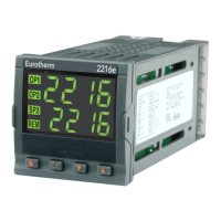
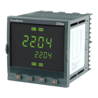
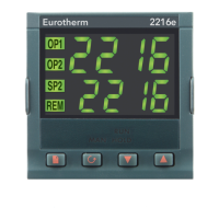
1. Model Modèle Modell
2216e 1/16 DIN
2208e 1/8 DIN
2204e 1/4 DIN
8. Manual
Manuel
nleitung
XXX No manual
Pas de manuel
Keine Handbuch
ENG English
Anglais
Englisch
FRA French
Français
Französisch
GER German
Allemand
Deutsch
ITA Italian
Italien
Italienisch
SPA Spanish
Espagnol
Spanisch
,
4, 5 & 6. Inputs/Outputs Entrées/Sorties Eingange
usgänge
1 2 3&4 (AA)
XX XX XX Not fitted Néant Kein
Relay Relais Relais
R1 R1 RF Unconfigured Non configuré Unkonfigurier
RU - - VP raise Ouverture de vanne Schrittregelausgang (Auf)
- RW - VP Lowe
Fermeture de vanne Schrittregelausgang (Zu)
RH RH RH PID Heating PID inverse Heizen
- RC RC PID Cooling PID direc
Kühlen
FH FH FH High alarm Alarme haute Maximalalarm
FL FL FL Low alarm Alarme Basse Minimalalarm
DB DB DB Band alarm Alarme de Bande Abweichungsbandalarm
DL DL DL Dev. low alarm Alarme Deviation basse Abweichungsalarm
Untersollwert
DH DH DH Dev high alarm Alarme Déviation haute Abweichungsalarm
Übersollwert
- AL AL High & Low Dév. Haute et Basse Sammelalarm 1 und 2
Logic Logique Logi
L1 L1 - Unconfigured Non configuré Unkonfigurier
LH LH - Heating PID inverse Heizen
- LC - Cooling PID direc
Kühlen
M1 - - PDS mode 1 Mode PDS 1 PDS Mode 1
M2 - - PDS mode 2
Mode PDS 2 PDS Mode 2
Triac Triac Triac
T1 T1 - Unconfigured Non configuré Unkonfigurier
TH TH - Heating PID inverse Heizen
- TC - Cooling PID direc
Kühlen
TU - - VP raise Ouverture de vanne Schrittregelausgang (Auf)
- TW - VP Lowe
Fermeture de vanne Schrittregelausgang (Zu)
DC – isolated
Régulation
analogique –isolé
Stetig: isoliert
D3 - Unconfigured Non configuré Unkonfigurier
Sortie PID inverse 0-20 mA Heizen
H7 - - 4-20mA heatin
Sortie PID inverse 4-20 mA Heizen
C6 - - 0-20mA coolin
0-20 mA Kühlen
C7 - - 4-20mA coolin
4-20 mAKühlen
Logic Input Entrée Logique Digital Eingang
- AM - Auto manual Auto/Manu Hand Auswahl
- S2 - Setpoint 2 Consigne 2 Sollwert 2
- AC - Alarm ack/rese
Acquittement alarme Alarmbestätigun
- EH - Integral hold Gel de l'intégrale Integral hold
- SB - Standby mode Mode "standby" Standby
- SR - PDS remote SP
select
Consigne externe PDS
Freigabe externer SP
- M5 - CTX mode 5 Entrée mesure couran
CTX Modus 5
PDS Alarms Entrée PDS
larm PDS
- - LF Heater break Défaut de charge PDS PDS Lastfehle
- - HF Current
monitoring
heater break
Défaut chauffage PDS PDS Heizelementfehle
- - SF Current
monitoring SSR
failure
Défaut contacteur
statique PDS
PDSIO SSR Fehle
DC Retransmission (isolated)
elect from table A
Retransmission analogique isolée Voir tableau A
DC Retransmission (isoliert)
iehe Tabelle A
Logik Eingang (nur OP2)
• Nicht von Fühlereingang isoliert.
• Schalten: 18 V DC bei 24 mA max
Logikausgang (SSR gesteuert und PDS)
• Nicht von Fühlereingang isoliert.
• Ausgang EIN Status: 18 V DC bei 24 mA
max
Triacausgang
• Isolierter Ausgang 240 V AC
• 1 A eff, 30 bis 264 V AC ohm’sch
Relaisausgang
• Form A, Schließer
• Isolierter Ausgang 240 V AC
• Kontakt Nennwert: 2 A, 264 V AC
ohm’sch
Ausgang 1/2 (OP1) / (OP2)
Sie können für die Ausgänge 1 und 2 zwischen
verschiedenen Modulen wählen.
Die Bestellcodierung und die
Verdrahtungshinweise auf dem Geräteaufkleber
geben Ihnen Informationen über die im Gerät
enthaltenen Module und deren Funktion.
Les sorties 1 et 2 peuvent être d'un quelconque
des types représentés ci-dessous,
Pour vérifier quels sont les modules qui sont
installés sur le régulateur et quelles sont les
fonctions pour lesquelles ils sont configurés, se
reporter au code de commande et aux
informations sur le câblage figurant sur les
étiquettes latérales du régulateur.
Entrée logique contacts (OP2 seulement)
• Non isolée par rapport à l'entrée capteur
• Commutation : 18 Vdc à 24mA maxi
Sortie Triac
• Sortie isolée 240 Vac
• 1 Aeff, de 30 à 264 Vac résistif
Sortie Logique (commande relais
statique SSR et PDS)
• Non isolée par rapport à l'entrée du
capteur
• Sortie Etat actif (ON) : 18 Vdc à 24 mA
maxi
Sortie Relais
• Forme A, normalement ouvert
• Sortie isolée 240Vac
• Pouvoir de coupure : 2 A 264 Vac résistive
Sortie 1/2 (OP1) / (OP2)
Output 1/2 (OP1) / (OP2)
• Not isolated from the sensor
input
• Switching: 18Vdc at 24mA max
• Not isolated from the sensor
input
• Output ON state: 18Vdc at
24mA max
• Isolated output 240Vac
• 1A rms, 30 to 264Vac resistive
• Form A, normally open
• Isolated output 240Vac
• Contact rating: 2A 264Vac
resistive
OP1
1A
1B
OP1
-
+
1A
1B
Outputs 1 and 2 can be any one of the types
shown below.
To check which outputs are installed, and
their configuration, refer to the ordering
code and the wiring information on the
controller side labels.
DC Ausgang (nur OP1)
• Isolierter Ausgang 240 V AC.
• Softwarekonfigurierbar: 0-20 mA oder 4-20
mA.
• Max. Leitungswiderstand: 500Ω
Sortie Analogique (OP1 seulement)
• Sortie isolée 240 Vac
• Configurable: par Logiciel 0-20 mA ou 4-20 mA
• Résistance de charge maxi. : 500 Ω
• Isolated 240Vac.
• Software configurable: 0-20mA
or 4-20mA.
• Max load resistance: 500Ω
OP2
2A
2B
-
+
OP1
1A
1B
-
+
OP2
2A
2B
OP2
2A
2B
+
-
1/2
Logic Output (SSR drive and PDS)
Relay Output
DC Output (OP1 only)
Logic Input (OP2 only)
1A
1B
OP1
2A
2B
OP2
Triac Output
2. Fit the IP65 sealing gasket behind the front
bezel of the controller
3. Insert the controller in its sleeve through the
cut-out.
4. Spring the panel retaining clips into place.
Secure the controller in position by holding
it level and pushing both retaining clips
forward.
5. Peel off the protective cover from the
display.
If the panel retaining clips subsequently need
to be removed, they can be unhooked from
the side with either your fingers or a
screwdriver.
Installation
1. Cut out the panel to the size shown.
(Not to scale)
Installation Installation
1. Bereiten Sie den Schalttafelausschnitt
nach der untenstehenden Abbildung vor.
(nicht maßstabsgerecht)
1. Effectuer la découpe dans le panneau aux
dimensions indiquées.
(Schéma non mis à l’échelle)
2. Monter le joint d'étanchéité IP65 derrière
la face avant du régulateur
3. Engager le régulateur dans la découpe
4. Positionner les clips de fixation. Maintenir
le régulateur et presser les clips de
fixation vers l'avant
5. Retirer le film de protection de l'afficheur.
S'il faut ultérieurement retirer les clips de
fixation pour extraire le régulateur du
panneau de commande, il est possible de les
décrocher avec les doigts ou un tournevis.
2. Wenn nötig, montieren Sie die IP65
Dichtung hinter den Frontrahmen des
Reglers.
3. Stecken Sie den Regler in den
Tafelausschnitt.
4. Bringen Sie die Halteklammern an ihren
Platz. Zum Sichern des Reglers halten Sie
das Gerät in Position und schieben Sie beide
Klammern gegen den Schalttafelausschnitt.
5. Lösen Sie die Schutzfolie von der Anzeige.
Die Halteklammern können Sie einfach mit
den Fingern oder einem Schraubendreher
entfernen.
Panel Cutout
Découpe Panneau
Schalttafelausschnitt
E 45mm (- 0.0 + 0.6)
1.77inch
(-0.00, +0.02)
F 92mm (- 0.0 + 0.8)
3.62 inch (-0.00 +0.03)
2216e
F
F
2208e 2204e
E
E
E
F
Recommended
Minimum Spacing
Espace minimum
recommandé
Minimalabstände
zwischen Reglern
G 38mm (1.5in)
H 10mm (0.4in)
G
2208e 2204e
H
2216e