9
Operation and Maintenance Instructions
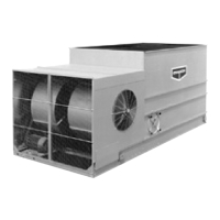
On induced draft belt driven units provided with externally mounted motors (6, 8, 8.5, 12, 15 and 17 foot wide units), Figure 3, and
LSTB forced draft units, Figure 4, both J-type adjustment bolts on the adjustable motor base should have an equal amount of
exposed thread for proper sheave and belt alignment.
Figure 3 – Externally Mounted Motors
Figure 4 – LSTB Externally Mounted Motor
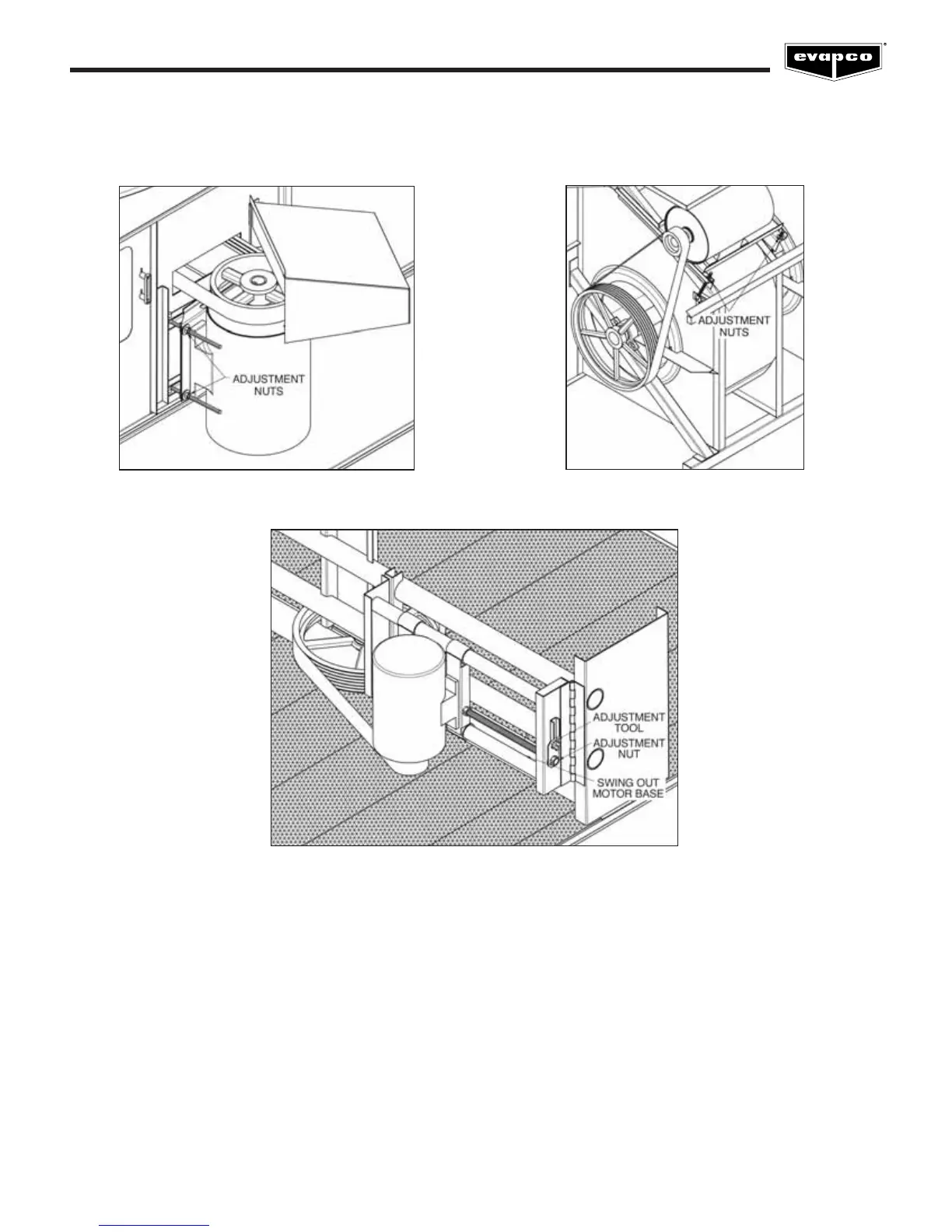
Figure 5 – Internally Mounted Motors
On induced draft belt driven units with internally mounted motors (10, 12, 14, 20, 24 and 28 foot wide units), Figure 5, and LPT units,
Figure 6, a motor adjustment tool is provided. The tool will be found on the adjustment nut. To use, place the hex end over the
adjustment nut. Tension the belt by turning the nut counterclockwise. When the belts are properly tensioned, tighten the lock nut.
 Loading...