EasyManua.ls Logo

EVAPCO LS Series - User Manual

Default Icon
16 pages
Print Icon
To Next Page IconTo Next Page
Loading...
Bulletin 122R-Metric
Rigging
and
Assembly Instructions
LS SERIES
FORCED DRAFT EVAPORATIVE CONDENSERS
AND CLOSED CIRCUIT COOLERS
For EVAPCO Authorized Parts and Service, Contact Your Local EVAPCO
Representative or the Local Mr. GoodTower
®
Service Provider
EVAPCO, Inc.
— World
Headquarters
& Research
/
Development Ce
n
t
e
r
EVAPCO, Inc. • P.O. Box 1300 • Westminster, MD 21158 USA
P
HONE: 410-756-2600 • FAX: 410-756-6450 • E-MAIL: marketing@evapco.com
EVAPCO
North
America
EVAPCO,
Inc.
World
Headquarters
P.O. Box 1300
Westminster, MD 21158 USA
Phone: 410-756-2600
Fax: 410-756-6450
E-mail: marketing@evapco.com
EVAPCO E
a
st
5151
Allendale La
n
e
T
a
n
e
ytow
n
,
MD 21787 USA
Phone:
410
-
756
-
2600
Fax:
410
-
756
-
6450
E-mail:
ma
rk
e
ti
ng
@e
va
p
co.co
m
EVAPCO
Mi
dwe
st
1723 York
R
o
a
d
Greenup,
IL
62428 USA
Phone:
217
-
923
-
3431
Fax:
217
-
923
-
3300
E-mail:
e
va
p
co
mw
@e
va
p
co
mw
.co
m
EVAPCO
W
e
st
1900 West
Almond A
ve
nu
e
Madera,
CA 93637 USA
Phone:
559
-
673
-
2207
Fax:
559
-
673
-
2378
E-mail: co
n
ta
ct@e
va
p
co
w
e
st.
co
m
EVAPCO I
owa
925
Quality
Dri
ve
Lake View,
IA
51450 USA
Phone:
712
-
657
-
3223
Fax:
712
-
657
-
3226
EVAPCO I
owa
Sales
& E
ng
i
ne
e
ri
ng
215 1st
Street,
NE
P.O. Box
88
Medford,
MN 55049 USA
Phone:
507
-
446
-
8005
Fax:
507
-
446
-
8239
E-mail:
e
va
p
co
mn
@e
va
p
co
mn
.co
m
Refrigeration
V
a
lv
e
s
&
Systems
Co
rpo
ra
ti
on
A
wholly owned
subsidiary
of
EVAPCO,
I
n
c.
1520
C
ro
ssw
i
nd
Dr
.
Bryan, TX 77808 USA
Phone:
979
-
778
-
0095
Fax:
979
-
778
-
0030
E-mail:
rvs@rvsco
rp
.co
m
McCormack
Coil
Company,
I
nc.
A
wholly owned
subsidiary
of
EVAPCO,
I
n
c.
P.O. Box
1727
6333 S.W.
Lakeview
B
ou
l
e
va
rd
Lake
Oswego,
OR 97035 USA
Phone:
503
-
639
-
2137
Fax:
503
-
639
-
1800
E-mail:
mail@mmccoil.com
E
v
a
p
T
e
ch,
I
nc.
A
wholly owned
subsidiary
of
EVAPCO,
I
n
c.
8331
Nieman
R
o
a
d
Lenexa,
KS 66214 USA
Phone:
913
-
322
-
5165
Fax:
913
-
322
-
5166
E-mail:
ma
rk
e
ti
ng
@e
va
p
te
ch.co
m
T
ower
Components, I
nc.
A
wholly owned
subsidiary
of
EVAPCO,
I
n
c.
5960 US HWY
64
E
R
a
mse
u
r
,
NC
27316
Phone:
336
-
824
-
2102
Fax:
336
-
824
-
2190
E-mail:
m
a
il
@
t
o
w
e
r
c
o
m
pon
e
n
t
si
n
c
.
c
o
m
EVAPCO
N
ewto
n
701 East
Jourdan
Stre
e
t
Newton,
IL
62448 USA
Phone:
618
-
783
-
3433
Fax:
618
-
783
-
3499
E-mail:
e
va
p
co
mw
@e
va
p
co
mw
.co
m
EVAPCO
Europe
EVAPCO
Europe, N.V.
European
Headquarters
Industrieterrein Oost 4010
3700 Tongeren, Belgium
Phone: (32) 12-395029
Fax: (32) 12-238527
E-mail: evapco.europe@evapco.be
EVAPCO E
urop
e
,
S
.
r
.
l
.
Via Ciro
Menotti 10
I
-
20017
Passirana
di
R
ho
Milan,
I
ta
ly
Phone:
(39)
02
-
939
-
9041
Fax: (39)
02
-
935
-
00840
E-mail:
e
va
p
co
e
u
ro
p
e
@e
va
p
co.
i
t
EVAPCO E
urop
e
,
S
.
r
.
l
.
Via Dosso
2
23020
Piateda Sondrio,
I
ta
ly
EVAPCO E
urop
e
,
G
mb
H
B
o
ve
rt
22
D-40670
Meerbusch,
Ge
rma
n
y
Phone:
(49)
2159
-
69560
Fax: (49)
2159
-
695611
E-mail: i
n
fo
@e
va
p
co.
d
e
Flex coil
a
/
s
A
wholly owned subsidiary of
EVAPCO,
I
n
c.
Knøsgårdvej 115
DK-9440
Aabybro
De
n
ma
rk
Phone:
(45) 9824
4999
Fax: (45) 9824
4990
E-mail: i
n
fo
@fl
e
xco
il
.
d
k
EVAPCO S.A.
(Pty.)
L
td
.
A
licensed manufacturer of
EVAPCO,
I
n
c.
18
Quality
R
o
a
d
I
sa
ndo
1600
R
e
pub
lic of
South
Afri
ca
Phone:
(27)
11
-
392
-
6630
Fax: (27)
11
-
392
-
6615
E-mail:
e
va
p
co
@e
va
p
co.co.
za
E
v
a
p
E
g
y
p
t
E
ng
i
n
ee
r
i
ng
I
ndu
s
t
r
i
e
s
C
o
.
A
licensed manufacturer of
EVAPCO,
I
n
c.
5 El Nasr
R
o
a
d
Nasr City, Cairo,
E
g
yp
t
EVAPCO
Asia/Pacific
EVAPCO
Asia/Pacific Headquarters
1159 Luoning Rd. Baoshan Industrial Zone
Shanghai, P. R. China, Postal Code: 200949
Phone: (86) 21-6687-7786
Fax: (86) 21-6687-7008
E-mail: marketing@evapcochina.com
E
q
ui
pme
nt
Co.,
L
td
.
1159
Louning
Rd.,
B
a
o
sh
a
n
I
ndu
stri
a
l
Z
on
e
Shanghai,
P.R. China,
Postal
Code:
200949
Phone:
(86)
21
-
6687
-
7786
Fax: (86)
21
-
6687
-
7008
E-mail:
m
a
r
k
e
t
i
ng
@e
va
p
coch
i
n
a
.co
m
Beijing
EVAPCO
Re
fri
g
e
ra
ti
on
E
q
ui
pme
nt
Co.,
L
td
.
Yan Qi
I
ndu
stri
a
l
Development
Di
stri
ct
Huai Rou
C
oun
ty
Beijing, P.R. China,
Postal
Code:
101407
Phone:
(86) 10
6166
-
7238
Fax: (86) 10
6166
-
7395
E-mail:
e
va
p
co
b
j
@e
va
p
coch
i
n
a
.co
m
EVAPCO
Australia (Pty.)
L
td
.
34-42
Melbourne
R
o
a
d
P.O. Box
436
R
i
ve
rsto
n
e
,
N.S.W.
Australia 2765
Phone:
(61) 2
9627
-
3322
Fax: (61) 2
9627
-
1715
E-mail:
sa
l
e
s@e
va
p
co.co
m.
a
u
E
v
a
p
T
e
ch
Asia Pacific Sdn. Bhd
A
wholly owned
subsidiary
of
EvapTech,
I
n
c.
IOI
Business Park, 2/F
Unit 20
Persiaran Puchong
Jaya
Se
l
a
ta
n
B
a
nd
a
r
Puchong
Ja
ya,
47170
Puchong, Selangor,
Ma
l
a
ysi
a
Phone:
(60-3) 8070
7255
Fax: (60-3) 8070
5731
E-mail:
ma
rk
e
ti
ng
-
a
p
@e
va
p
te
ch.co
m
EVAPCO...S
PECIALISTS IN
H
EAT
T
R
A
N
S
F
ER
P
RODUCTS
AND
S
ER
V
I
CES
.
Phone:
2 02
24022866
/
2 02
24044997
Fax: 2 02
24044667
/
2 02
24044668
E-mail:
P
r
i
m
a
c
oo
l
@
li
n
k.
n
e
t
/
S
h
a
d
y
@
p
r
i
m
a
c
oo
l
.
n
e
t
EVAPCO
(Shanghai)
Re
fri
g
e
ra
ti
on
Visit EVAPCOʼ s Website at:
http://www
.evapco.com
Question and Answer IconNeed help?

Do you have a question about the EVAPCO LS Series and is the answer not in the manual?

Summary

Method of Shipment

Storage and General Handling

International Building Code Provisions

Structural Steel Support

Pan;Fan Section Rigging

Complete Unit Rigging

Applying Sealer Tape

Rigging the Coil Section

Assembly of Coil Section to Pan;Fan Section

Optional Hood Section Installation

Optional Discharge Attenuation Section

Optional Intake Attenuation Section

Motor Installation

Final Assembly and Start-up Details

Float Valve Adjustment

Adjust float valve for correct water level in the basin.

Fan Rotation Check

Verify fan rotation direction and motor current draw.

Pump Rotation Check

Confirm pump rotation direction after filling the basin.

Freeze Protection

Water Treatment Guidelines

Routine Maintenance

Accessory Location Checklist

Overview

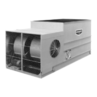
This document outlines the rigging and assembly instructions for EVAPCO LS Series Forced Draft Evaporative Condensers and Closed Circuit Coolers. These units are specialized heat transfer products designed for industrial refrigeration and HVAC applications.

Function Description

The LS Series units are evaporative condensers and closed circuit coolers that facilitate heat transfer by evaporating water, thereby cooling a process fluid or condensing a refrigerant. They are designed for forced draft operation, meaning air is forced through the unit by fans. The units can be shipped either fully assembled (smaller units) or in sections (pan-fan section and coil section) for larger models, requiring on-site assembly. Optional components like discharge hoods, discharge attenuation, and intake attenuation can also be integrated.

Important Technical Specifications

Method of Shipment and Rigging: Units are shipped either fully assembled or with the top section(s) separate from the bottom section(s). Mating flanges are designed for a waterproof joint when sealed and bolted. Rigging involves using U-bolts or lift points provided on the pan-fan and coil sections. For extended lifts, safety slings and spreader bars are recommended to prevent damage to upper flanges.

Structural Steel Support: Two structural "I" beams running the length of the unit are required for support, positioned underneath the outer flanges. Mounting holes (19mm diameter) are located in the bottom flange for bolting to the structural steel. Beams should be level to within 1.5mm in 1m. Maximum beam deflection under the unit should be 1/360 of the unit length, not exceeding 13mm, calculated using 55% of the operating weight as a uniform load.

International Building Code (IBC) Provisions: The LS Series Coolers and Condensers are IBC 2006 compliant up to 1g (7kPa wind-load) with standard construction and up to 5.12g (7kPa wind-load) with additional structural modifications. All attached items (piping, ductwork, conduit, electrical connections) must be independently reviewed and isolated to meet applicable wind and seismic loads, requiring flexible attachment to the EVAPCO unit.

Rigging Dimensions (Minimum "H" Dimension for Pan/Fan Section): The minimum "H" dimension (vertical clearance for rigging) varies by unit footprint:

  • 1.2 x 1.8m: 2.5m
  • 1.2 x 2.7m: 3.1m
  • 1.2 x 3.6m: 4.6m
  • 1.2 x 5.4m: 5.8m
  • 1.6 x 3.6m: 4.6m
  • 1.6 x 5.4m: 5.8m
  • 2.4 x 3.6m: 4.6m
  • 2.4 x 5.4m: 5.8m
  • 2.4 x 7.3m: 7.7m
  • 2.4 x 11m: 11.6m
  • 3 x 3.6m: 4.6m
  • 3 x 5.4m: 5.8m
  • 3 x 7.3m: 7.7m
  • 3 x 11m: 11.6m

Rigging Dimensions (Minimum "H" Dimension for Coil Section): The minimum "H" dimension for coil sections also varies by unit footprint:

  • 1.2 x 1.8m: 2.5m
  • 1.2 x 2.7m: 3.1m
  • 1.2 x 3.6m: 4.6m
  • 1.2 x 5.4m: 5.8m
  • 1.6 x 3.6m: 4.6m
  • 1.6 x 5.4m: 5.8m
  • 2.4 x 3.6m: 4.6m
  • 2.4 x 5.4m: 5.8m
  • 2.4 x 7.3m: 4.6m
  • 2.4 x 11m: 5.8m
  • 3 x 3.6m: 4.6m
  • 3 x 5.4m: 5.8m
  • 3 x 7.3m: 4.6m
  • 3 x 11m: 5.8m

Rigging Dimensions (Minimum "H" Dimension for Complete Unit): For complete units, the minimum "H" dimension is:

  • 1.2 x 1.8m: 2.5m
  • 1.2 x 2.7m: 3.1m

Rigging Dimensions (Minimum "H" Dimension for Discharge Hoods/Attenuation and Intake Attenuation): These components share similar "H" dimensions to the coil sections, varying from 2.5m to 5.8m depending on the footprint.

Float Valve Adjustment: Pre-set at the factory, but requires checking after rigging. The float valve should be adjusted so the center of the float is 25mm below the center of the overflow connections when fully closed. Operating pressure range is between 140kPa and 340kPa.

Minimum Operating Level: The minimum operating water level varies by unit footprint:

  • 1.2 x 1.8m, 1.2 x 2.7m, 1.2 x 3.6m, 1.2 x 5.4m, 1.6 x 3.6m, 1.6 x 5.4m: 3.4m
  • 2.4 x 3.6m, 2.4 x 5.4m, 2.4 x 11m, 3 x 5.4m, 3 x 11m: 4.6m
  • 2.4 x 7.3m, 3 x 3.6m, 3 x 7.3m: 3.7m

Usage Features

Assembly Process:

  1. Pan/Fan Section Rigging: U-bolts or lift points are used for lifting and positioning. Units up to 5.4m long have 4 lift points; 7.3m and 2.4m x 11m units have 6 lift points; other 11m units have 8 lift points. Extended lifts require slings and spreader bars.
  2. Sealer Tape Application: After the bottom section is bolted to the support steel, sealer tape is applied over the mounting hole centerline on side flanges, with two overlapping strips on end flanges. For units with two coil sections, tape is applied to all internal flanges.
  3. Coil Section Rigging: U-bolts or lift points in the four corners (and center for larger units) are used. Eliminator sections should be removed before lifting. Extended lifts require slings and spreader bars.
  4. Coil Section Assembly to Pan/Fan Section: Loose parts are removed from the pan. Flanges are wiped clean. The coil section is lowered onto the pan-fan section, guided by drift pins in mounting holes. Fasteners are installed from corners towards the center.
  5. Complete Unit Rigging: For fully assembled units, U-bolts or lift points in the coil section below the eliminators are used. Extended lifts require slings and spreader bars.
  6. Optional Hood/Attenuation Section Assembly: These sections are rigged separately using U-bolts. Sealer tape is applied to the top flanges of the coil section before lowering the hood/attenuation. Fasteners are installed in all four corners (and middle for 5.4m long hoods).
  7. Motor Installation (1.2m and 1.6m wide models): Involves installing motor bases, pivot bolts, J-bolts, belts, and aligning sheaves. Belts should not be overtensioned, with approximately 13mm deflection at the center with moderate hand pressure. Motor guard is then fastened.
  8. Final Assembly and Start-up: Remove shipping materials. Connect pump discharge line. Ensure bleed-off line and valve are properly installed and open. Check strainer. Protective air inlet screens are provided (bottom screens recommended for elevated units). Adjust float valve. Check fan and pump rotation.

Storage: Units should not be covered with tarps or other coverings if stored before installation to prevent excessive heat buildup and PVC eliminator damage. For extended storage (beyond six months), rotate fan and motor shafts monthly, and purge/regrease fan shaft bearings before start-up.

Freeze Protection: The simplest method is a remote sump, allowing water to drain back when the pump is off. If a remote sump is not used, pan heaters are available, but external water lines, pump, and piping up to the overflow level must be heat traced and insulated. Pan heaters only prevent freezing when fans are off. Units cannot be operated dry (fans on, pump off) unless the pan is completely drained.

Maintenance Features

Water Treatment: Proper water treatment is essential. Galvanized equipment should be passivated before startup to avoid white rust. Both spray water and process fluid in the coil must be maintained with a water treatment program for efficient operation and extended service life. EVAPCO's Engineering Bulletin 36 provides information on passivation and white rust, and the Operation and Maintenance Instructions detail recommended water chemistry.

General Maintenance: Regular maintenance is crucial for full performance. Refer to the operation and maintenance instructions supplied with the unit for specific procedures.

EVAPCO LS Series Specifications

General IconGeneral
BrandEVAPCO
ModelLS Series
CategoryAccessories
LanguageEnglish

Related product manuals