LS Se
ies Coolers and Condensers
3
The supporting “I” beams should be level to within 1.5mm in 1m before setting the unit. Do not level the unit by shimming
between the bottom flange and the beams as this will not provide proper longitudinal support.
NOTE: Consult IBC 2006 for required steel support layout and structural design.
Table 1 – Steel Support Dimensions
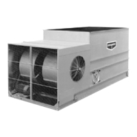
Rigging
Pan/Fan
Secti
on
U-bolts or similar lifting points are located in the pan-fan section for lifting and final positioning purposes as shown below in Figures
2, 3 and 4. Units with lengths up to 5.4m have 4 total lift points. Units with lengths of 7.3m and 2.4m x 11m long units have 6 lift points.
All other 11m long units have 8 lift points. See Table 2 for the minimum “H” dimensions for rigging the pan-fan assembly.
NOTE
: Use all of the U-bolts or lift points provided for lifting.
Figure 2 – Pan/Fan Section
(up to 5.4m Long)
Figure 3 – Pan/Fan Section
(7.3m Long and 2.4 x11m Long - 6 lift points shown)
Unit
Footprint (m)
B1(Unit Only)
(mm)
B2 Unit with
Intake Attn.
(mm)
A
(mm)
1.2×1.8 1235 3038 1826
1.2×2.7 1235 3038 2724
1.2×3.6 1235 3038 3645
1.2×5.4 1235 3038 5486
1.6×3.6 1661 3467 3645
1.6×5.4 1661 3467 5490
2.4×3.6 2388 4191 3651
2.4×5.4 2388 4191 5486
2.4×7.3 2388 4191 7341
2.4×11 2388 4191 11030
3×3.6 2991 4794 3648
3×5.4 2991 4794 5493
3×7.3 2991 4794 7334
3×11 2991 4794 11020