10
LS Series Coolers and Condensers
Optional Discharge Attenuation
Secti
on
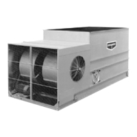
Some units may be supplied with an optional discharge attenuation section. This section will ship from the factory as a separate
item or mounted on top of either the pan-fan section or coil section to reduce freight charges. Each discharge attenuation section
is equipped with U-bolts located at the four corners for lifting and final positioning (Figure 17). Always use safety slings for
extended lifts or where any hazard exists.
NOTE: When combined with other sections, the attenuation must be removed prior to any lift. In all cases the hood
section must be rigged as a separate part.
Once the coil section has been secured to the pan-fan section, wipe the top flanges to remove any dirt or moisture. Place sealer
tape over the mounting hole centerline on the side flanges. Apply two strips of sealer tape, one partially overlapping the other, on
the end flanges as shown in Figures 7 and 8.
Lower the attenuation section to within several inches of the coil section making sure the two sections do not touch and the sealer
tape is not disturbed. Place drift pins (see Figure 18) in at least 3 of the corner mounting holes and gradually lower the coil section
into place using the drift pins to guide the section down accurately onto the mating flange. On 5.4m and 7.3m long sections,
drift pins should be used midway along the sides as well.
Place fasteners in all four corner bolt holes. Then continue to install the rest of the fasteners working from the corners toward the
center, using drift pins to align the holes. A fastener must be installed in every hole on the side flanges although none are required
on the end flanges. For units with two attenuation sections, mount the first as described, and then follow the same procedure for
the second section.
Figure 17 – Discharge Attenuator Rigging Figure 18 – Discharge Attenuator Installation Instructions
 Loading...