LS Series Coolers and Condensers
11
Unit
Footprint(m)
Minimum
“H”(m)
2.4 x 5.4 5.8
2.4 x 7.3 4.6
2.4 x 11 5.8
3 x 3.6 4.6
3 x 5.4 5.8
3 x 7.3 4.6
3 x 11 5.8
Optional Intake
A
ttenuati
on
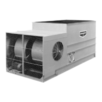
Some units may be supplied with an optional intake attenuation section. This section will ship from the factory as a separate item
or mounted on top of either the pan-fan section or coil section to reduce freight charges. Each intake attenuation section is
equipped with U-bolts located at the four corners for lifting and final positioning (Figure 19). Always use safety slings for extended
lifts or where any hazard exists.
NOTE: When combined with other sections, the attenuation must be removed prior to any lift. In all cases the attenuation
section must be rigged as a separate part.
Move the attenuation section to within several inches of the fan intake section. Place drift pins (see Figure 18) in at least 3 of the
corner mounting holes and gradually move the coil section into place using the drift pins to guide the section accurately onto the
mating flange. On 5.4m and 7.3m long sections, drift pins should be used midway along the sides as well. See Table 6 for the
minimum “H” dimensions for rigging the inlet attenuation for both standard and extended lifts.
Table 6 – Minimum “H” Dimension for Rigging Inlet Attenuation
Unit
Footprint(m)
Minimum
“H”(m)
1.2 x 1.8 2.5
1.2 x 2.7 3.1
1.2 x 3.6 4.6
1.2 x 5.4 5.8
1.6 x 3.6 4.6
1.6 x 5.4 5.8
2.4 x 3.6 4.6
Figure 19 – Complete Attenuator Rigging