13
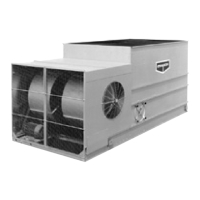
LS Series Coolers and Condensers
Unit
Footprint(m)
Minimum Level
(m)
2.4 x 5.4 4.6
2.4 x 7.3 3.7
2.4 x 11 4.6
3 x 3.6 3.7
3 x 5.4 4.6
3 x 7.3 3.7
3 x 11 4.6
Final Assembly
and Start
-up Details
Shipping Materials - Remove any wood chocks, spare parts, or miscellaneous items that have been placed inside the unit for
shipping purposes. Clean all debris from the basin.
Pump Discharge Line - Connect the riser pipe from the pump discharge on the pan-fan section to the riser pipe on the coil section
using the flexible connection and hose clamps provided.
Bleed-off Line - A bleed-off line and valve are installed on the unit when shipped with a pump. On units shipped without a pump
(remote sump applications) make sure a bleed-off line and valve are properly sized and installed on the discharge side of the pump
and connected to a convenient drain. In either case, the bleed-off valve should be fully open.
Strainer - Check the strainer in the basin to ensure that it is in its proper location over the pump suction.
Screens - Protective air inlet screens are provided across the front of the fan section of all models. Screens are not provided on
the bottom of the fan section since most of the units are mounted on steel beams, either on the roof or at ground level. If units are
installed in an elevated position, bottom screens are recommended for safety protection and should be provided by the installing
contractor.
Float Valve Adjustment - The float valve is pre-set at the factory, however adjustment should be checked after rigging. The float
valve should be adjusted so that the center of the float is 25mm below the center of the overflow connections when the valve is in the
fully closed position. Raise or lower the float by using the wing nuts on the vertical threaded rod. Do not adjust the horizontal rod.
During normal operation, the water level will drop 76mm to 100mm below the overflow in condensers and coolers. See Table 7 for
normal operating level for the LS Series units. Note: The float valve has an available operating pressure between 140kPa and
340 kPa.
Fan Rotation - Bump start and check the fans for proper rotation. Directional arrows are placed on the outside of centrifugal fan
housings or on the inside of axial fan cylinders. Note, unless the unit has been sized for dry operation, the fan motor will overamp
unless the pump is also running.
Pump Rotation - Once the basin is filled with water, bump start and check the pump for proper rotation. Directional arrows are
found on the pump impeller housing.
Table 7 – Minimum Operating Level
Unit
Footprint(m)
Minimum Level
(m)
1.2 x 1.8 3.4
1.2 x 2.7 3.4
1.2 x 3.6 3.4
1.2 x 5.4 3.4
1.6 x 3.6 3.4
1.6 x 5.4 3.4
2.4 x 3.6 3.7