EVCO S.p.A. | EV3 Basic Split | Instruction sheet ver. 1.0 | Code 1043BSE103 | Page 3 of 3 | PT 49/18
99
F9
10
evaporator fans off delay from
compressor off
0... 240 s
if F0 = 2 or 5
100
F11 15.0 condenser fans on threshold 0... 99 °C/°F
101
F12
30
condenser fans off delay from
compressor off
0... 240 s
if P4 ≠ 1
102
F13
2
condenser fans regulation
threshold differential
1... 25 °C/°F
0-10 V condenser fans pro-
portional band if Ao1 = 2
(relative to F11, F11 + F13)
103
F14
10
100 % start-up time for 0-10 V
condenser fans
0... 240 s
104
F15
100
maximum percentage 0-10 V
condenser fans in energy saving
0... 100 %
105
F17
60
time evaporator fans off in low
humidity
0... 240 s
if u1c... u5c = 16, activates
speed 2 evaporator fans
106
F18
10
time evaporator fans on in low
humidity
0... 240 s
107
F19
0
interval activation reversible
condenser fans
0... 240 h
108
F20
0
reversible condenser fans on
time
0... 240 min
109
F30
0
setting percentage 0-10 V evapo-
rator fans in normal function
mode
0 = touch SET key twice
1 = with F33
2 = automatic with F1, F31,
F32 and F36
110
F31
50
percentage 0-10 V output for
evaporator fans with minimum
capacity
0... 100 %
if F31>F32, F32 is relevant
111
F32
100
percentage 0-10 V output for
evaporator fans with maximum
capacity
0... 100 %
if F32<F31, F31 is relevant
112
F33
100
percentage 0-10 V evaporator
fans in normal function
F31... F32
113
F34
10
Start up time 0-10 V
evaporator fans at F35
0... 240 s
114
F35
100
percentage 0-10 V evaporator
fans from power-on
0... 100%
115
F36
10
0-10 V evaporator fans
proportional band (relative to F1)
1... 25 °C/°F
F1-F36
116
F37
0
maximum percentage 0-10 V
evaporator fans in energy saving
0... 100%
NO.
PAR. DEF. DIGITAL INPUTS MIN... MAX.
117
i0
5
door switch input function
0 = disabled
1 = compressor + evapora-
tor fans off
2 = evaporator fans off
3 = cabinet light on
4 = compressor + evapora-
tor fans off, cabinet light
on
5 = evaporator fans off,
cabinet light on
118
i1
0
door switch input activation
0 = with contact closed
1 = with contact open
119
i2
30
door open alarm delay
-1... 120 min
-1 = disabled
120
i3
15
maximum time for inhibiting
regulation with door open
-1... 120 min
-1 = until closed
121
i5
0
multi-purpose input function
0 = disabled
1 = energy saving
2 = alarm iA
3 = alarm iSd
4 = load 1 operated by on
key
5 = load 2 operated by on
key
6 = switches device on/off
7 = alarm LP
8 = alarm C1t
9 = alarm C2t
122
i6
0
multi-purpose input activation
0 = with contact closed
1 = with contact open
123
i7
0
multi-purpose input alarm delay
0... 120 min
if i5 = 3 or 7, compressor on
delay from alarm reset
124
i8
0
number of multi-purpose input
activations for high pressure
alarm
0... 15
0 = disabled
if i5 = 3
125
i9
240
counter reset time for high pres-
sure alarm
1... 999 min
126
i10
0
door closed consecutive time for
energy saving
0... 999 min
after cabinet temperature <
SP
0 = disabled
127
i13
180
number of door openings for de-
frost
0... 240
0 = disabled
128
i14
32
door open consecutive time for
defrost
0... 240 min
0 = disabled
NO.
PAR. DEF. DIGITAL OUTPUTS MIN... MAX.
129
u1c
0
K1 relay configuration
0 = compressor 1
1 = compressor 2
2 = evaporator fans
3 = condenser fans
4 = defrosting
5 = cabinet light
6 = demisting
7 = door heaters
8 = heaters for neutral zone
9 = dripping heaters
10 = button-operated load 1
11 = button-operated load 2
12 = alarm
13 = on/stand-by
14 = evaporator fans 2
15 = defrosting 2
16 = speed 2 evaporator fans
17 = reversible cond. fans
18 = speed 2 cond. fans
130
u2c 2 K2 relay configuration like u1c
131
u3c 4 K3 relay configuration like u1c
132
u4c 5 K4 relay configuration like u1c
133
u5c
3
K5 relay configuration
0 = PWM compressor
1... 18 like u1c
134
u2
0
enable cabinet light and load in
stand-by using the key
0 = no 1 = yes
in manual mode
135
u3
0
alarm relay activation
0 = with alarm not active
1 = with alarm active
136
u4 1 enable silencing alarm output 0 = no 1 = yes
137
u5 -1.0 door heaters on threshold -99... 99 °C/°F
138
u5d
2.0
door heaters on threshold differ-
ential
1... 25 °C/°F
139
u6
5
duration demisting on
1... 120 min
1 = on/off by pressing key
140
u7
-5.0
neutral zone for heating thresh-
old (relative to setpoint)
-99... 99 °C/°F
differential = 2 °C/4 °F
setpoint + u7
141
u9 1 enable alarm buzzer 0 = no 1 = yes
NO.
PAR. DEF. ANALOGUE OUTPUTS MIN... MAX.
142
Ao1
5
analogue output configuration
0 = PWM compressor (r15)
1 = 0-10 V compressor
2 = 0-10 V cond. fans
3 = 0-10 V evap. fans
4 = disabled
5 = disabled
NO.
PAR. DEF. CLOCK MIN... MAX.
143
Hr0 0 enable clock 0 = no 1 = yes
NO.
PAR. DEF. ENERGY SAVING (if r5 = 0) MIN... MAX.
144
HE2
0
maximum duration energy saving
0... 999 min
0 = until door opened
NO.
PAR.
DEF.
ENERGY SAVING IN REAL TIME
(if r5 = 0; visible if Hr0=1)
MIN... MAX.
145
H01 0 energy saving time 0... 23 h
146
H02 0 maximum duration energy saving
0... 24 h
NO.
PAR.
DEF.
SWITCHING ON/OFF IN REAL
TIME (visible if Hr0=1)
MIN... MAX.
147
Hon
h-
time device switch-on
0... h-
h- = disabled
148
HoF
h-
time device switch-off
0... h-
h- = disabled
149
Hc1
h-
1st time reversible condenser
fans on
0... h-
h- = disabled
for time F20
150
Hc2
h-
2nd time reversible condenser
fans on
0... h-
h- = disabled
for time F20
NO.
PAR.
DEF.
DEFROSTING IN REAL TIME (if
d8 = 4; visible if Hr0=1)
MIN... MAX.
151
Hd1
h-
1st daily defrosting time
0... h-
h- = disabled
152
Hd2
h-
2nd daily defrosting time
0... h-
h- = disabled
153
Hd3
h-
3rd daily defrosting time
0... h-
h- = disabled
154
Hd4
h-
4th daily defrosting time
0... h-
h- = disabled
155
Hd5
h-
5th daily defrosting time
0... h-
h- = disabled
156
Hd6
h-
6th daily defrosting time
0... h-
h- = disabled
NO.
PAR. DEF. SECURITY MIN... MAX.
157
POF 1 enable ON/STAND-BY key 0 = no 1 = yes
158
Loc 1 enable keypad lock 0 = no 1 = yes
159
PAS -19 password -99... 999
160
PA1 426 1st level password -99... 999
161
PA2 824 2nd level password -99... 999
NO.
PAR.
DEF.
EVLINK DATA-LOGGING (visible
if Hr0=1)
MIN... MAX.
162
rE0 15 data logger sampling interval 0... 240 min
163
rE1
1
select temperature for data log-
ger
0 = none 1 = cabinet
2 = evaporator
3 = auxiliary
4 = cabinet and evaporator
5 = all
NO.
PAR. DEF. MODBUS MIN... MAX.
164
LA 247 MODBUS address 1... 247
165
Lb
2
MODBUS baud rate
0 = 2,400 baud
1 = 4,800 baud
2 = 9,600 baud
3 = 19,200 baud
166
LP
2
MODBUS parity
0 = none 1 = odd
2 = even
NO.
PAR. DEF. EVLINK MIN... MAX.
167
bLE
1
activate EVlink
0 = no 1 = yes
> 1 = reserved
8 ALARMS
CODE
MEANING RESET TO CORRECT
Pr1 cabinet probe alarm automatic - check P0
Pr2 evaporator probe alarm automatic - check the integrity of the probe
Pr3 auxiliary probe alarm automatic - check electrical connection
rtc clock alarm manual set date, time and day of the week
AL low temperature alarm automatic check A0, A1 and A2
AH high temperature alarm automatic check A4 and A5
id door open alarm automatic check i0 and i1
PF
power failure alarm
manual
- touch a key
- check electrical connection
COH high condensation signal automatic check C6
CSd
high condensation alarm
manual
- switch the device off and on
- check C7
iA multi-purpose input alarm automatic check i5 and i6
iSd
high pressure alarm
manual
- switch the device off and on
- check i5, i6, i8, i9
LP low pressure alarm automatic check i5 and i6
C1t
compressor thermal switch
alarm
automatic
check i5 and i6
C2t
compressor 2 thermal
switch alarm
automatic
check i5 and i6
dFd
defrost timeout alarm
manual
- touch a key
- check d2, d3 and d11
9 TECHNICAL SPECIFICATIONS
Purpose of the control device: function controller.
Construction of the control device: built-in electronic device.
Housing:
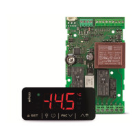
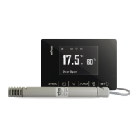
user interface: black, self-extinguishing control module: open frame board.
Category of heat and fire resistance: D.
Measurements:
user interface: 75.0 x 33.0 x 39.5 mm
(2 15/16 x 1 5/16 x 1 9/16 in)
control module: 66.5 x 107.5 x 31.0 mm (2
5/8 x 4 1/4 x 1 1/4 in).
Mounting methods for the control device:
user interface: to be fitted to a panel, snap-in
brackets provided
control module: to be installed on an electri-
cal panel, on spacers (not provided).
Degree of protection provided by the casing:
user interface: IP65 (front) control module: IP00.
Connection method:
user interface: plug-in screw terminal blocks
for wires up to 2.5 mm²
control module:
- fixed screw terminal blocks for wires up to
2.5 mm²
- Pico-Blade connector.
Maximum permitted length for connection cables:
user-interface-control module: 10 m (32.8 ft) power supply: 10 m (32.8 ft)
analogue inputs: 10 m (32.8 ft) digital inputs: 10 m (32.8 ft)
analogue outputs: 3 m (9.84 ft) digital outputs: 10 m (32.8 ft).
Operating temperature: from 0 to 60 °C (from 32 to 140 °F)
Storage temperature: from -25 to 70 °C (from -13 to 158 °F).
Operating humidity:
relative humidity without condensate from
10 to 90%.
Pollution status of the control device: 2.
Compliance:
RoHS 2011/65/EC
WEEE 2012/19/EU
REACH (EC) Regulation no.
1907/2006
EMC 2014/30/EU LVD 2014/35/EU.
Power supply:
user interface: powered by the control mod-
ule
control module:
- 230 VAC (+10% -15%), 50/60 Hz (±3
Hz), max. 2 VA insulated in EV3SB22N7
and EV3SB24N7
- 115... 230 VAC (+10 % -15%), 50/60 Hz
(±3 Hz), max. 3.2 VA insulated in
EV3SB54N9.
Earthing methods for the control device: none.
Rated impulse-withstand voltage:
- 4 KV in EV3SB22N7 and EV3SB24N7
- 2.5 KV in EV3SB54N9.
Over-voltage category:
- III in EV3SB22N7 and EV3SB24N7
- II in EV3SB54N9.
Software class and structure: A.
Analogue inputs:
- 1 for PTC or NTC probes (cabinet probe) in
EV3SB22
- 2 for PTC or NTC probes (cabinet probe
and evaporator probe) in EV3SB24 and
EV3SB54
PTC probes: Type of sensor: KTY 81-121 (990 @ 25 °C, 77 °F)
Measurement field: from -50 to 150 °C (from -58 to 302 °F)
Resolution: 0.1 °C (1 °F).
NTC probes: Type of sensor: ß3435 (10 K @ 25 °C, 77 °F)
Measurement field: from -40 to 105 °C (from -40 to 221 °F)
Resolution: 0.1 °C (1 °F).
Digital inputs:
1 dry contact (door switch); not available for
EV3SB22.
Other inputs:
- 1 input can be configured for analogue in-
put (evaporator probe) or digital input
(door switch, dry contact) for EV3SB22
- 1 input can be configured for analogue in-
put (auxiliary probe) or digital input
(multi-purpose, dry contact) for EV3SB24
and EV3SB54
Contact Type of contact: 5 VDC, 1.5 mA
dry: Power supply: none
Protection: none.
Analogue outputs:
1 for PWM or 0-10 V signal (compressor in-
verter; only available for EV3SB54).
Other outputs:
1 for 12 VDC max. 30 mA (only available for
EV3SB54).
Signal Power supply: 12 VDC (+16 % -25 %), 20 mA max.
PWM: Frequency: 0... 150 Hz
Protection: none.
0-10 V
Signal:
Minimum applicable imped-
ance:
1 K
Resolution: 0.01 V
Digital outputs:
- 2 with sealed electro-mechanical relay in
compliance with the EN 60079-15 stan-
dard in EV3SB22
- 4 with sealed electro-mechanical relay in
compliance with the EN 60079-15 stan-
dard in EV3SB24 and EV3SB54.
K1 relay: SPST, 16 A res. @ 250 VAC.
K2 relay:
SPST, 5 A res. @ 250 VAC (not available for
EV3SB22).
K3 relay:
SPDT, 8 A res. @ 250 VAC (not available for
EV3SB22).
K4 relay: SPDT, 16 A res. @ 250 VAC.
Type 1 or Type 2 actions: type 1.
Additional features of Type 1 or Type 2 ac-
tions:
C.
Displays: custom display, 3 digit, with function icons.
Alarm buzzer: built-in.
Communications ports:
1 TTL MODBUS slave port for EVJKEY pro-
gramming key, EVconnect app, EPoCA re-
mote monitoring system or for BMS.
N.B.
The device must be disposed of according to local regulations governing the collection
of electrical and electronic equipment.
This document and the solutions contained therein are the intellectual property of EVCO and thus pro-
tected by the Italian Intellectual Property Rights Code (CPI). EVCO imposes an absolute ban on the full
or partial reproduction and disclosure of the content other than with the express approval of EVCO. The
customer (manufacturer, installer or end user) assumes all responsibility for the configuration of the de-
vice.
EVCO accepts no liability for any possible errors in this document and reserves the right to make any
changes, at any time without prejudice to the essential functional and safety features of the equipment.
EVCO S.p.A.
Via Feltre 81, 32036 Sedico (BL) ITALY
Tel. +39 0437/8422 | Fax +39 0437/83648
email info@evco.it | web www.evco.it
 Loading...