EVCO S.p.A. | EV3411M | Instruction sheet ver. 1.0 | Code 1043411ME103 | Page 1 of 2 | PT 46/17
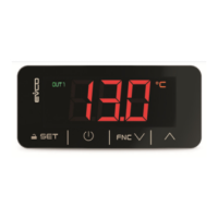
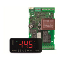
EV3411 Multi-sensor
Universal controllers with one regulation output for industrial applications
EN
ENGLISH
- power supply 230 VAC or 12-24 VAC/DC (according to the model)
- multi-sensor input (PTC/NTC/J/K/Pt 100/Pt 1000/Ni 120/0-20 mA/4-20 mA/0-10 V/
2-10 V)
- multi-purpose input
- analogue output 0-10V/PWM (alternatively to relay K1)
- K1 relay 16 A res. @ 250 VAC (alternatively to the analog output)
- alarm buzzer
- TTL MODBUS slave port for programming key, for EVlink Wi-Fi module (EPoCA system),
for EVlink BLE module (app EVconnect) or for TTL/RS-485 (BMS) serial interface
- on-off/PID control
- hot or cold mode regulation.
1 MEASUREMENTS AND INSTALLATION
Measurements in mm (in); 59.0 (2 5/16) depth with fixed screw terminal blocks, 81,5
(3 3/16) depth with plug-in screw terminal blocks.
To be fitted to a panel, snap-in brackets provided.
INSTALLATION PRECAUTIONS
- the thickness of the panel must be between 0.8 and 2.0 mm (1/32 and 1/16 in);
- ensure that the working conditions are within the limits stated in the TECHNICAL
SPECIFICATIONS section;
- do not install the device close to heat sources, equipment with a strong magnetic field,
in places subject to direct sunlight, rain, damp, excessive dust, mechanical vibrations
or shocks;
- in compliance with safety regulations, the device must be installed properly to ensure
adequate protection from contact with electrical parts. All protective parts must be
fixed in such a way as to need the aid of a tool to remove them.
2 ELECTRICAL CONNECTION
N.B.
- use cables of an adequate section for the current running through them.
- ensure that the thermocouple is properly insulated from contact with metal parts or
use already insulated thermocouples.
- if necessary, extend the thermocouple cable using a compensating cable.
- in the models with power supply 12-24 VAC/DC, the analog output is available on
condition that the device is powered at 24 VAC/DC.
- to reduce any electromagnetic interference locate the power cables as far away as
possible from the signal cables.
PRECAUTIONS FOR ELECTRICAL CONNECTION
- if using an electrical or pneumatic screwdriver, adjust the tightening torque;
- if the device has been moved from a cold to a warm place, humidity may have caused
condensation to form inside. Wait about an hour before switching on the power;
- make sure that the supply voltage, electrical frequency and power are within the set
limits. See the section TECHNICAL SPECIFICATIONS;
- disconnect the power supply before carrying out any type of maintenance;
- do not use the device as safety device;
- for repairs and for further information, contact the EVCO sales network.
3 FIRST-TIME USE
1. Install following the instructions given in the section MEASUREMENTS AND
INSTALLATION.
2. Power up the device as set out in the section ELECTRICAL CONNECTION: an internal
test will start up.
The test normally takes a few seconds; when it is finished the display will switch off.
3. Configure the device as shown in the section Setting configuration parameters.
Recommended configuration parameters for first-time use.
PAR.
DEF.
PARAMETER
MIN... MAX.
SP 0.0 setpoint r1... r2
P0
2
type of probe
set the parameter before
connecting the probe
0 = PTC 1 = NTC
2 = J 3 = K
4 =
Pt 100 3 wires
5 =
Pt 100 2 wires
6 =
Pt 1000 3 wires
7 =
Pt 1000 2 wires
8 = 4-20 mA 9 = 0-20 mA
10 = 2-10 V 11= 0-10 V
12 =
Ni 120 3 wires
13=
Ni 120 2 wires
P2 0 temperature measurement unit
0 = °C 1 = °F
r5
0
hot or cold mode regulation regulator
0 = cold mode
1 = hot mode
uA
0
outputs configuration
0 = analog output not enabled, K1
relay with regulator
1 = analog output proportional to
the regulation temperature, K1
relay not enabled
2 = analog outputwith regulator, K1
relay not enabled
ub
0 type of analogue output
0 = 0-10 V 1 = PWM
Then check that the remaining settings are appropriate; see the section
CONFIGURATION PARAMETERS.
4. Disconnect the device from the mains.
5. Make the electrical connection as shown in the section ELECTRICAL CONNECTION
without powering up the device.
6. When connecting to an RS-485 network, connect the EVIF22TSX interface. To use the
device with the EPoCA remote monitoring system, connect the EVIF25TWX module. To
use the device with the Evconnect app, connect the EVIF25TBX module; see the relative
instruction sheets. If using EVIF22TSX, set the bLe parameter to 0.
7. Power up the device.
4 USER INTERFACE AND MAIN FUNCTIONS
4.1 Switching the device on/off
1.
If POF = 1 (default), touch the ON/STAND-BY key for 4s.
If the device is switched on, the display will show the P5 value ("regulation temperature"
default); if the display shows an alarm code, see the section ALARMS.
LED
ON
OFF
FLASHING
OUT1
regulator active
-
- regulator protection active
- setpoint being set
unused
-
-
OUT2
unused
-
-
alarm active
-
-
analogue output active
-
-
device switched off
device switched on
device being switched on/off
°C/°F
temperature display
-
-
%
percentage display
-
-
Bar
pressure display
-
-
When 30s have elapsed without the keys being pressed, the display will show the "Loc" label
and the keypad will lock automatically.
4.2 Unlocking the keypad
Touch a key for 1s: the display will show the label “UnL”.
4.3 Setting the setpoint
Check that the keypad is not locked.
1.
Touch the SET key: the display will show the label “SP”.
2.
Touch the UP or DOWN key within 15s to set the value within the
limits r1 and r2 (default "0... 350”).
3.
Touch the SET key (or take no action for 15s).
4.4 Silencing the buzzer (if A13 = 1)
Touch a key.
5 FUNCTION MODES
Cold mode regulation (r5 = 0).
Hot mode regulation (r5 = 1).
Operation with analogue output 0-10 V (ub = 0, default) proportional to the regulation
temperature (ua = 1, default).
Operation with analogue output PWM (ub = 1) proportional to the regulation temperature
(ua = 1, default).
6 ADDITIONAL FUNCTIONS
6.1 Displaying/setting the value delivered by the analogue output
Check that the keypad is not locked.
1.
Touch the DOWN key for 4s.
2.
Touch the UP or DOWN key within 15s to select a label.
LAB.
DESCRIPTION
uA
displaying the value delivered by the analogue output
uM
modifying the value delivered by the analogue output
3.
Touch the SET key.
4.
Touch the UP or DOWN key to set the value (to select uM).
5.
Touch the SET key.
6.
Touch the ON/STAND-BY key (or take no action for 60s) to exit
the procedure.
6.2 Displaying the number of start-ups of the relay
Check that the keypad is not locked.
1.
Touch the DOWN key for 4s.
2.
Touch the UP or DOWN key within 15s to select a label.
LAB.
DESCRIPTION
nS1
display of the number of start-ups of the K1 relay in thousands
3.
Touch the SET key.
4.
Touch the ON/STAND-BY key (or take no action for 60s) to exit
the procedure.
6.3 Displaying the temperature detected by the regulation probe
Check that the keypad is not locked.
1.
Touch the DOWN key for 4s.
2.
Touch the UP or DOWN key within 15s to select a label.
LAB.
DESCRIPTION
Pb1
regulation temperature
3.
Touch the SET key.
4.
Touch the ON/STAND-BY key (or take no action for 60s) to exit
the procedure.
7 SETTINGS
7.1 Setting configuration parameters
N.B.
Changing parameter P2 from °C to °F (and vice versa) causes the value of the
parameters whose unit of measurement is °C or °F to be changed automatically.
1.
Touch the SET key for 4s: the display will show the label “PA”.
2.
Touch the SET key.
3.
Touch the UP or DOWN key within 15s to set the PAS value
(default "-19").
4.
Touch the SET key (or take no action for 15s): the display will
show the label “SP”.
5.
Touch the UP or DOWN key to select a parameter.
6.
Touch the SET key.
7.
Touch the UP or DOWN key within 15s to set the value.
8.
Touch the SET key (or take no action for 15s).
9.
Touch the SET key for 4s (or take no action for 60s) to exit the
procedure.
7.2 Restoring factory settings (default) and saving customised settings
N.B.
- Check that the factory settings are appropriate; see the section CONFIGURATION
PARAMETERS.
- Saving customised settings overwrites the factory settings.
1.
Touch the SET key for 4s: the display will show the label “PA”.
2.
Touch the SET key.
3.
Touch the UP or DOWN key within 15s to set the value.
VAL.
DESCRIPTION
149 value for restoring the factory information (default)
161 value for saving customised settings
4.
Touch the SET key (or take no action for 15s): the display will
show the label “dEF” (for setting the “149” value) or the label
“MAP” (for setting the “161” value)
5.
Touch the SET key.
6.
Touch the UP or DOWN key within 15s to set "4".
7.
Touch the SET key (or take no action for 15s): the display will
show “- - -“ flashing for 4s, after which the device will exit the
procedure.
8. Disconnect the device from the power supply.
9.
Touch the SET key for 2s before action 6 to exit the procedure
beforehand.
8 CONFIGURATION PARAMETERS
N.
PAR.
DEF.
SETPOINT MIN... MAX.
1 SP 0.0 setpoint r1... r2
N. PAR. DEF. ANALOGUE INPUTS
MIN... MAX.
2 CA1 0.0 regulation probe offset
-25... 25 °C/°F
3
P0
2
type of probe
0 = PTC 1 = NTC
2 = J 3 = K
4 = Pt 100 3 wires
5 = Pt 100 2 wires
6 = Pt 1000 3 wires
7 = Pt 1000 2 wires
8 = 4-20 mA 9 = 0-20 mA
10 = 2-10 V 11 = 0-10 V
12 = Ni 120 3 wires
13 = Ni 120 2 wires