EasyManua.ls Logo

Evco EV3B24 - User Manual

Evco EV3B24
6 pages
Print Icon
To Next Page IconTo Next Page
Loading...
EVCO S.p.A. | EV3B24 | Data sheet ver. 1.0 | Code 1043B24E104 | Page 1 of 6 | PT 12/15
EV3B24 Basic controller for low temperature bottle coolers, cabinets, refrigerated
cabinets, tables and pizza counters, with energy saving features
GB ENGLISH
IMPORTANT
Read this document thoroughly before installation and before use of the device and follow all recommendations; keep this
document with the device for future consultation.
Only use the device in the way described in this document; do not use the same as a safety device.
The device must be disposed of in compliance with local standards regarding the collection of electric and electronic
equipment.
1 DIMENSIONS AND INSTALLATION
1.1 Dimensions
Dimensions are expressed in mm (in).
59.0 (2.322) is the depth with fixed screw connection terminal blocks; 81.5 (3.208) is the depth with removable screw
connection terminal blocks.
- disconnect the device power supply before proceeding
with any type of maintenance
- position the power cables as far away as possible from
the signal cables
- for repairs and information regarding the device, contact
the EVCO sales network.
3 USER INTERFACE
3.1 Preliminary notes
Operating statuses:
- “on” status (the device is powered and is on; utilities
may be on
- stand-by” status (the device is powered but is switched
off via software; utilities are off
- the “off” status: the device is not powered; utilities are
off.
Hereafter, if the POF parameter is set to 0, with the word
“switch-on” means the passage from “off” status to “on”
status; the word “switch-off” means the passage from “on”
status to “off” status.
If the POF parameter is set to 1, with the word “switch-on”
means the passage from “stand-by” status to “on” status;
the word “switch-off” means the passage from “on” status
to “stand-by” status.
When the power is switched back on, the device displays the
status that it was in at the time it was disconnected.
3.2 Manual switch on/off of the device
If the POF parameter is set to 0:
1. Connect/disconnect the device power supply.
If the POF parameter is set to 1:
2. Make sure that the keyboard is not locked and that no
procedure is in progress.
3. Touch the
key for 4 s: the LED will flash,
after which it will turn off/on.
3.3 The display
If the device is switched on, during normal operation, the
display will show the magnitude established with P5, except
during defrost, when the device will show the magnitude
established with d6 parameter.
If the device is switched off (“stand-by” status), the display
will be switched off; the
LED shall be on.
If the device is in "low consumption" mode, the display will
be switched off and the
LED shall be on.
3.4 Temperature display as detected by the
probes
1. Make sure that the keyboard is not locked and that no
procedure is in progress.
2. Touch the
key for 4 s: the display will show the
first label available.
3. Touch the
or key to select a label.
4. Touch the
.
The following table shows the correspondence between the
labels and the temperature displayed.
Label Displayed temperature
Pb1 if the P4 parameter is set to 0, 1 or 2, room
temperature
if the P4 parameter is set to 3, incoming air tempe-
rature
Pb2 evaporator temperature
Pb3 if the P4 parameter is set to 1, condenser tempe-
rature
if the P4 parameter is set to 2, critical temperature
if the P4 parameter is set to 3, outgoing air tempe-
rature
Pb4 CPT temperature
To exit the procedure:
5. Touch the
key or do not operate for 60 s.
6. Touch the
key.
If the evaporator probe èis absent (that is to say, if the P3
parameter is set to 0), the “Pb2” label shall not be displayed.
If the fourth inlet function is to be a multifunction inlet (that
is to say, if the P4 parameter is set to 0) the “Pb3” label
shall not be displayed.
If the fourth inlet function is not to be an outgoing air prove
(that is to say, if the P4 parameter is not set to 3) the “Pb4
label shall not be displayed.
3.5 Compressor operation hours
To show the compressor operation hours:
1. Make sure that the keyboard is not locked and that no
procedure is in progress.
2. Touch the
key for 4 s: the display will show the
first label available.
3. Touch the
or key to select “CH”.
4. Touch the
key.
To exit the procedure:
5. Touch the
key or do not operate for 60 s.
6. Touch the
key.
To cancel the compressor operation hours:
7. From step 3. touch the
or key to select
rCH”.
8. Touch the
key.
9. Touch the
or key within 15 s to set
149”.
10. Touch the
key or do not operate for 15 s: the
display will show a flashing “- - -” for 4 s, after which
the device will exit the procedure.
3.6 “Rapid cooling” function enabling/disabling
1. Make sure that the keyboard is not locked and that no
procedure is in progress, that the “rapid cooling” function
is not in progress, that there are no defrosting, dripping
or evaporator fan stop operations in progress, that the
r5 parameter is set to 0 and that the r8 parameter is set
to 1.
2. Touch the
key : the °C LED or the °F LED will
falsh/stop flashing; see also r6 e r7 parameters.
3.7 “Rapid heating” function enabling/disabling
1. Make sure that the keyboard is not locked and that no
procedure is in progress, and that the r5 and r8
parameters are set to 1.
2. Touch the
key : the °C LED or the °F LED will
falsh/stop flashing; see also r6 e r7 parameters.
3.8 “Energy saving” function enabling/disabling
in manual mode
1. Make sure that the keyboard is not locked and that no
procedure is in progress, that the r5 parameter is set to
0 and that the r8 parameter is set to 2.
2. Touch the
key : the LED will turn on/off; see
also r4, F4, F5 e HE2 parameters.
3.9 Defrost manual activation
1. Make sure that the keyboard is not locked and that no
procedure is in progress, that the “rapid cooling” function
is not in progress.
2. Touch the
key for 4 s.
If the evaporator probe functions as a defrost probe (that is
to say, if the P3 parameter is set to 1) and when the defrost
starts the evaporator temperature exceeds the value set
with the d2 parameter, the defrost shall not be activated.
3.10 Room light switch-on/off in manual mode
1. Make sure that no procedure is in progress and that the
u1 parameter is set to 0; see also u2 parameter.
2. Touch the
key: the “AUX” LED will turn on/off.
3.11 Demister heating elements activation
1. Make sure that no procedure is in progress and that the
u1 parameter is set to 1.
2. Touch the
key for 4 s: the “AUX” LED will turn
on; see also u6 parameter.
3.12 Turning on/off the auxiliary output in manual
mode
1. Make sure that the keyboard is not locked, that no
procedure is in progress and that the u1 parameter is
set to 2; see also u2 parameter.
2. Touch the
key: the “AUX” LED will turn on/off.
3.13 Keyboard locking/unlocking
To lock the keyboard proceed as follows:
1. Make sure no procedure is in progress.
2. Do not operate for 30 s: the display will show the
message “Loc” for 1 s and the keybord shall lock
automatically.
To unlock the keyboard:
3. Touch a key for 1 s: the display will show the message
UnL” for 1 s.
1.2 Installation
Panel installation with snap-in brackets.
1.3 Installation warnings
- the thickness of the panel on which the devise is to be
installed must be between 0.8 and 2.0 mm (0.031 and
0.078 in)
- make sure that the device work conditions (tempera-
ture of use, humidity, etc.) lie within the limits indi-
cated; see chapter 8
- do not install the device near to any heat sources (heating
elements, hot air ducts etc.), equipment containing
powerful magnets (large diffusers, etc.), areas affected
by direct sunlight, rain, humidity, excessive dust,
mechanical vibrations or shocks
- in compliance with safety standards, the device must
be installed correctly and in a way to protect against
any contact with electric parts; all parts that ensure
protection must be fixed in a way that they cannot be
removed without the use of tools.
2 ELECTRIC CONNECTION
2.1 Electric connection
2.2 Warnings for the electric connection
- do not use electric or pneumatic screwdrivers on the
device terminal board
- if the device has been taken from a cold to hot place,
humidity could condense inside; wait about 1 hour
before powering it
- check that the power supply voltage, mains frequency
and electric power fall within the set limits; see chapter
8
Question and Answer IconNeed help?

Do you have a question about the Evco EV3B24 and is the answer not in the manual?

Evco EV3B24 Specifications

General IconGeneral
Operating Temperature-10 to 55 °C
Front Panel ProtectionIP65
ProtectionIP65
Power Supply12-24 Vac/dc or 115-230 Vac
Input Voltage12-24 Vac/dc or 115-230 Vac
Dimensions74x32x60 mm

Summary

Dimensions and Installation

Device Dimensions

Details the physical dimensions of the device in millimeters and inches.

Panel Installation

Explains panel installation using snap-in brackets.

Installation Warnings

Lists critical warnings for installation, including panel thickness and environmental conditions.

Electric Connection

Electrical Wiring

Details the electrical connections and wiring diagrams for the device.

Electric Connection Warnings

Provides crucial warnings for electrical connections, emphasizing proper tool usage and environmental considerations.

User Interface Operations

Operating Statuses

Describes the different operating statuses: 'on', 'stand-by', and 'off'.

Manual Device Switching

Details the procedure for manually switching the device on or off based on POF parameter.

Display Information

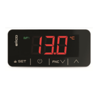
Explains what information is shown on the display during different operating modes.

Probe Temperature Display

Guides users on how to view temperatures detected by various probes on the device display.

Compressor Operation Hours

Instructions on how to view and cancel compressor operation hours.

Rapid Cooling Function Control

Explains how to enable or disable the "Rapid cooling" function.

Rapid Heating Function Control

Explains how to enable or disable the "Rapid heating" function.

Energy Saving Function Control

Details the process for enabling/disabling the "Energy saving" function manually.

Manual Defrost Activation

Provides instructions for manually activating the defrost function.

Manual Room Light Control

Explains how to manually switch the room light on or off.

Demister Heating Activation

Guides on how to activate the demister heating elements.

Manual Auxiliary Output Control

Details how to manually turn the auxiliary output on or off.

Keyboard Locking and Unlocking

Explains the procedure for locking and unlocking the device's keyboard.

Device Settings

Setting Working Setpoint

Details the steps to set the primary working setpoint for the device.

Configuration Parameter Setup

Guides on accessing and setting various configuration parameters for the device.

Restoring Manufacturer Settings

Explains how to restore the device to its original manufacturer's settings.

Indicator Lights and Signals

Signal Meanings

Explains the meaning of various LEDs and signals on the device, indicating its status.

Compressor LED

Describes the meaning of the compressor LED, indicating its operational status.

Defrost LED

Explains the defrost LED's function, indicating defrost cycles or related statuses.

Evaporator Fan LED

Describes the evaporator fan LED, indicating its on/off or standstill status.

Auxiliary LED (AUX)

Explains the auxiliary LED, indicating manual control of room light or demister.

Temperature Unit LEDs (°C; °F)

Indicates the device's selected unit of measurement for temperature.

Stand-by Indicator LED

Describes the 'on/stand-by' LED, indicating the device's standby status.

Alarm Codes and Solutions

Minimum Temperature Alarm (AL)

Details the minimum temperature alarm (AL), its causes, and consequences.

Maximum Temperature Alarm (AH)

Explains the maximum temperature alarm (AH), including causes and effects.

Door Switch Input Alarm (id)

Describes the door switch input alarm (id), its causes, and main consequences.

Multifunction Input Alarm (¡A)

Details the multifunction input alarm (¡A), its causes, and main consequences.

Condenser Overheated Alarm (COH)

Explains the condenser overheated alarm (COH), its causes, and consequences.

Compressor Shut Down Alarm (CSd)

Describes the compressor shut down alarm (CSd), its causes, and consequences.

Compressor Thermal Protection Alarm (Cth)

Details the compressor thermal protection alarm (Cth), its causes, and consequences.

Global Thermal Protection Alarm (th)

Explains the global thermal protection alarm (th), its causes, and consequences.

Defrost Alarm (dFd)

Describes the defrost alarm (dFd) when maximum time is reached, its causes, and consequences.

Technical Data Specifications

Device Purpose and Construction

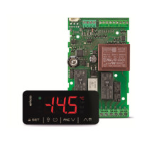
States the primary purpose and describes the construction of the command device.

Physical Dimensions and Mounting

Provides detailed dimensions and explains the panel mounting method.

Connection and Environmental Data

Details connection methods, operating/storage conditions, and environmental standards.

Power Supply and Electrical Ratings

Details the device's power supply requirements and electrical ratings.

Analog Input Configuration

Describes the analog inputs, including probe types and configurability.

Setpoint and Parameter Configuration

Working Setpoint Parameters

Details parameters related to the working setpoint, including min, max, and default values.

Configuration Parameter Table

Presents a table of configuration parameters with their ranges and default values.

Main Regulator Parameters

Setpoint Differential (r0, r12)

Defines parameters for working setpoint differential and its type.

Setpoint Limits (r1, r2)

Defines the minimum and maximum working setpoint parameters.

Energy Saving Setpoint Adjustment (r4)

Defines the 'r4' parameter for setpoint increase during "energy saving" function.

Cooling;Heating Mode (r5)

Defines the 'r5' parameter for selecting between cooling and heating operation.

Rapid Cooling;Heating Control (r6, r7, r8)

Defines parameters for rapid cooling/heating setpoint adjustment and duration.

Compressor Protection System Parameters

Compressor Switch-On Delays (CO, C3)

Defines parameters for delay in switching on compressor after device activation and minimum switch-on time.

Compressor Switch-Off Durations (C2, C4, C5)

Defines parameters for compressor switch-off durations, including during probe errors.

Condenser Temperature Alarms (C6, C7, C8)

Defines parameters for condenser temperature thresholds for overheating and shutdown alarms.

Maintenance Request Trigger (C10)

Defines the 'C10' parameter for the number of compressor operation hours triggering a maintenance request.

Defrost Cycle Parameters

Defrost Interval and Type (d0, d1)

Defines parameters for the defrost interval and the type of defrost method.

Defrost End Temperature and Duration (d2, d3)

Defines parameters for the evaporator temperature at the end of defrost and its maximum duration.

Defrost Activation Conditions (d4, d5)

Defines parameters for conditions that trigger defrost activation and delays.

Defrost Display and Dripping (d6, d7)

Defines parameters for the magnitude displayed during defrost and the duration of dripping.

Defrost Activation Methods (d8)

Defines the 'd8' parameter for selecting the defrost activation method.

Evaporator Temperature Settings (d9, d19)

Defines parameters related to evaporator temperature thresholds for defrost suspension and activation.

Defrost Alarm and Minimum Operation (d11, d15)

Defines parameters for defrost alarm conditions and minimum compressor switch-on time for defrost.

Pre-Dripping and Defrost Interval (d16, d18)

Defines parameters for pre-dripping duration and defrost interval under specific conditions.

Consecutive Compressor Operation for Defrost (d20, d21)

Defines parameters for minimum consecutive compressor operation for defrost activation.

Temperature Alarm Parameters

Evaporator Temperature for Alarm Suspension (d22)

Defines the 'd22' parameter for evaporator temperature to suspend temperature alarms.

Minimum Temperature Alarm Threshold (A1)

Defines the 'A1' parameter for the minimum temperature alarm threshold.

Maximum Temperature Alarm Threshold (A4)

Defines the 'A4' parameter for the maximum temperature alarm threshold.

Temperature Alarm Delays (A6, A7, A8, A9)

Defines parameters for delays in temperature alarm triggering.

Temperature Alarm Differential (A11)

Defines the 'A11' parameter as the differential for A1 and A4 parameters.

Fan Control Parameters

Evaporator Fan Activity (F0, F2)

Defines parameters for evaporator fan activity during normal operation and defrost/dripping.

Evaporator Fan Temperature Control (F1, F7)

Defines parameters for evaporator fan switch-off and restart temperatures.

Evaporator Fan Stop;Start Durations (F3, F4, F5, F12, F15)

Defines parameters for evaporator fan stop/start durations and operation when compressor is off.

Condenser Fan Control (F9, F11)

Defines parameters for condenser fan switch-on temperature and stop delay.

Digital Input Functions

Door Micro Input Effects (i0, i1, i2, i3)

Defines parameters for door micro input effects, contact type, and alarm delay.

Multifunction Input Effects (i5, i6, i7)

Defines parameters for multifunction input effects, contact type, and alarm delay.

Energy Saving and Defrost Input Triggers (i10, i13, i14)

Defines parameters for energy saving activation time and defrost triggers via door switch inputs.

Digital Output Configurations

Utility Management via K4 Output (u1)

Defines the 'u1' parameter for utilities managed by the K4 digital output.

Condenser Fan Output Control (u2)

Defines the 'u2' parameter for condenser fan control.

Door Heating Elements Control (u5)

Defines the 'u5' parameter for controlling door heating elements.

Demister Heating Elements Duration (u6)

Defines the 'u6' parameter for the duration of demister heating elements operation.

Neutral Area Heating Elements Control (u7)

Defines the 'u7' parameter for controlling neutral area operation heating elements.

On;Stand-by Output (u9)

Defines the 'u9' parameter for the ON/STAND-BY output.

Energy Saving and Stand-by Functions

Manual Energy Saving Duration (HE2)

Defines the 'HE2' parameter for the maximum duration of the "energy saving" function activated manually.

Low Consumption Function Interval (HE3)

Defines the 'HE3' parameter for the time interval before activating the "low consumption" function.

Various Device Settings

Key Activation Setting (POF)

Defines the 'POF' parameter for key activation settings.

Configuration Parameter Password (PAS)

Defines the 'PAS' parameter for accessing configuration parameters with a password.

Related product manuals