EVCO S.p.A. | EV3B24 | Data sheet ver. 1.0 | Code 1043B24E104 | Page 3 of 6 | PT 12/15
When the cause of the error disappears, the device restores
normal operation.
8 TECHNICAL DATA
8.1 Technical data
Purpose of the command device: operating command
device.
Construction of the command device: built-in elec-
tronic device.
Container: grey self-extinguishing.
Heat and fire protection class: D.
Dimensions: according to model:
- 75,0 x 33,0 x 59,0 mm (2,952 x 1,299 x 2,322 in;
L x H x P) with fixed screw connection terminal blocks
- 75,0 x 33,0 x 81,5 mm (2,952 x 1,299 x 3,208 in;
L x H x P) with removable screw connection terminal
blocks.
Method of mounting the command device: on panel,
with snap-in brackets.
Shell protection rating: IP65 (the front one).
Connection method: according to model:
- fixed screw connection terminal blocks for wires up to
2.5 mm² (0.0038 in²): power supply, analog inputs,
digital inputs and digital outputs
- removable screw connection terminal blocks for wires
up to 2.5 mm² (0.0038 in²): power supply, analog
inputs, digital inputs and digital outputs.
The maximum lengths of the connection cables are:
- power supply: 10 m (32.8 ft)
- analog inputs: 10 m (32.8 ft)
- digital inputs: 10 m (32.8 ft)
- digital outputs: 10 m (32.8 ft).
Operating temperature: from 0 to 55 °C (from 32 to 131 °F).
Storage temperature: from -25 to 70 °C (from -13 to 158 °F).
Humidity for use: from 10 to 90 % relative humidity
without condensate.
Command device pollution situation: 2.
Environmental standards:
- RoHS 2011/65/CE
- WEEE 2012/19/EU
- REACH (CE) regulation n. 1907/2006.
EMC standards:
- EN 60730-1
- IEC 60730-1.
Power supply: 115... 230 VAC (+10 % -15 %), 50... 60
Hz (±3 Hz), 3.2 VA max.
Control device grounding method: none.
Rated impulse voltage: 2.5 KV.
Overvoltage category: II.
Class and structure of software: A.
Analog inputs: 2 inputs (room temperature probe or inlet
air probe and evaporator probe) configurable via configura-
tion parameter for PTC or NTC probes.
Analog inputs PTC (990 Ω @ 25 °C, 77 °F)
Type of sensor: KTY 81-121.
Measurement field: from -50 to 150 °C (from -58
to 302 °F).
Resolution: 0,1 °C (1 °F).
Analog inputs NTC (10 KΩ @ 25 °C, 77 °F)
Type of sensor: ß3435.
Measurement field: from -40 to 105 °C (from -40
to 221 °F).
Resolution: 0,1 °C (1 °F).
Digital inputs: 1 input (door switch input).
Digital inputs (free of voltage contact 5 VDC 2 mA)
Other inputs: 1 input settable by way of a configuration
parameter for analog (condenser probe, critical temperature
probe or outflowing air probe) or digital (multifunction input)
inputs.
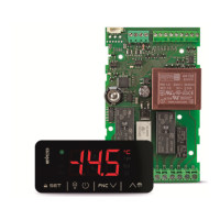
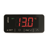
Displays: 3 digit custom display, with function icons.
Digital outputs:
- 1 output (SPST electromechanical relay with 16 A res.
@ 250 VAC) for compressor management
- 1 output (SPST electromechanical relay with 8 A res. @
250 VAC) for defrost management
- 1 output (SPST electromechanical relay with 5 A res. @
250 VAC) for evaporator fan management
- 1 output (SPST electromechanical relay with 5 A res. @
250 VAC) for the management of room lighting, demister
heating elements, auxiliary output, alarm output, door
heating elements, neutral area operation heating
elements , condenser fan or the on/stand-by output.
The maximum allowable current on the loads in 10 A.
The device guarantees double insulation between each
connector of the digital outputs and the other parts of the
device.
Type 1 or Type 2 actions: type 1.
Complementary features of Type 1 or Type 2 actions:
C.
9 WORKING SETPOINT AND CONFIGURATION PARAMETERS
9.1 Working Setpoint
MIN. MAX. U.M. DEF. WORKING SETPOINT
r1 r2 °C/°F (1) 0,0 working setpoint; see also r0 and r12
9.2 Configuration parameters
PARAM. MIN. MAX. U.M. DEF. WORKING SETPOINT
SP r1 r2 °C/°F (1) 0,0 working setpoint; see also r0 and r12
PARAM. MIN. MAX. U.M. DEF. ANALOG INPUTS
CA1 -25 25,0 °C/°F (1) 0,0 if P4 = 0, 1 or 2, room probe offset
if P4 = 3, incoming air probe offset
CA2 -25 25,0 °C/°F (1) 0,0 evaporator probe offset
CA3 -25 25,0 °C/°F (1) 0,0 if P4 = 1, condenser probe offset
if P4 = 2, critical temperature probe offset
if P4 = 3, outgoing air probe offset
P0 0 1 - - - 1 probe type
0 = PTC
1 = NTC
P1 0 1 - - - 1 degree Celsius decimal point (during normal operation)
1 = YES
P2 0 1 - - - 0 unit of measurement for temperature (2)
0 = °C (Celsius degree; resolution depends on P1 parameter)
1 = °F (Fahrenheit degree; resolution is 1 °F)
P3 0 2 - - - 1 evaporator probe function
0 = absent probe
1 = defrost probe and probe determining the activity of the evaporator fan
2 = probe determining the activity of the evaporator fan
P4 0 3 - - - 0 fourth inlet function
0 = multifunction input (digital input)
1 = condenser probe (analog input )
2 = critical temperature probe (analog input )
3 = outlet air probe (analog input ) (3)
P5 0 4 - - - 0 magnitude displayed during normal operation
0 = if P4 = 0, 1 or 2, room temperature
if P4 = 3, CPT temperature
1 = working setpoint
2 = evaporator temperature

 Loading...