EVCO S.p.A. | EVJ LCD | Instruction sheet ver. 3.2 | Code 104VJLCDE323 | Page 2 of 2 | PT 16/19
2.2.4 Insertion of the RS-485 port termination resistor
To insert the RS-485 port termination resistor, place micro-switch 2 in position ON. Micro-
switch 1 is reserved EVCO.
The micro-switch is at the back of the device.
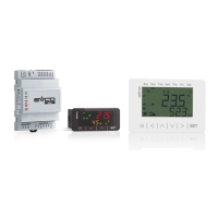
2.3 Models for wall mounting with back-slot for in-wall box
2.3.1 Connectors and parts
Connector 1
No.
DESCRIPTION
1 device power supply (115... 230 VAC)
2 device power supply (115... 230 VAC)
3 DO2 digital output normally open contact (1 A res. @ 250 VAC)
4 DO1 digital output normally open contact (1 A res. @ 250 VAC)
5 DO1 and DO2 digital outputs common contact (max. 2 A)
Connector 2
No.
DESCRIPTION
6 AI2 analog input (NTC)
7 AI1 analog input (NTC)
8 AI1 and AI2 analog inputs reference (GND)
9 INTRABUS port data (IB)
10 INTRABUS port reference (GND)
Temperature (AI3) and humidity (AI5) sensor: according to the model.
Bluetooth Low Energy sensor: according to the model.
2.3.2 Electrical connection
PRECAUTIONS FOR ELECTRICAL CONNECTION
- If using an electrical or pneumatic screwdriver, adjust the tightening torque
- If the device has been moved from a cold to a warm place, the humidity may have
caused condensation to form inside. Wait about an hour before switching on the power
- Make sure that the supply voltage, electrical frequency and power are within the set
limits. See the section TECHNICAL SPECIFICATIONS
- Disconnect the power supply before doing any type of maintenance
- Do not use the device as safety device
- For repairs and for further information, contact the EVCO sales network; possible re-
turns without label data will not be accepted.
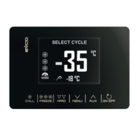
3 USER INTERFACE
3.1 Device configuration
N.B.
Turn off the power after changing the configuration.
Accessing the procedure.
1.
Touch the SET key for 7 s.
The display will show:
Upper line Mnu
Lower line InF
Accessing the menu.
2.
Touch the UP or DOWN key to select a menu.
The display will show:
Upper line Mnu
Lower line menu name.
3.
Touch the SET key.
The display will show:
Upper line the parameter
Lower line the parameter value
Setting configuration parameters of menu “PAr”.
3.
Touch the SET key.
The display will show:
Upper line PSU
Lower line 0000
4.
Touch the SET key again.
The display will show:
Upper line PSU
Lower line a value flashing
5.
Touch the UP or DOWN key to set “-019”.
6.
Touch the SET key.
7.
Touch the UP or DOWN key to select a parameter.
The display will show:
Upper line the parameter
Lower line the parameter value
8.
Touch the SET key.
The display will show:
Upper line the parameter
Lower line the parameter value flashing
9.
Touch the UP or DOWN key to set the value.
10.
Touch the SET key.
Returning to the previous displays.
11.
Touch the ON/STAND-BY key a few times.
4 CONFIGURATION PARAMETERS
N. PAR. DEF. “InF” MENU (READ ONLY) MIN... MAX.
1 Prn - project number -
2 Pru - project version -
3 Prr - project revision -
4 FUu - firmware version -
5 FUr - firmware revision -
6 FUS - firmware subversion -
7 HUu - hardware version -
8 HUr - hardware revision -
N. PAR. DEF. “PAr” MENU MIN... MAX.
9
bKU
15
backlight intensity
0... 100
fixed value 30 in the models
with incorporated tempera-
ture and humidity sensor
10
bKt
30
backlight timeout
0... 255 s
fixed value 30 in the models
with incorporated tempera-
ture and humidity sensor
11
bKM
tiME
backlight mode
off = off
on = on (not used in the
models with incorpo-
rated temperature
and humidity sensor)
tiME = with bKt
12
EU3 OFF enable compatibility with Vled 3 On... OFF
N. PAR. DEF. “nEt > Itb” MENU (READ ONLY) MIN... MAX.
13
nOd
4
INTRABUS node
1... 127
if EU3C = On, nOdE = 3
14
StA - INTRABUS status communication
OK... Err
15
nrH
-
number of received INTRABUS
packages
0... 999
16
ntH
-
number of transmitted INTRA-
BUS packages
0... 999
17
nEr
-
number of INTRABUS receipts in
error
0... 999
18
bAu - INTRABUS baud rate 19200
19
Stb 1 INTRABUS bit stop number 0... 2
20
PtY 2 INTRABUS parity 0... 2
N.
PAR.
DEF.
“NET > BLE” MENU (READ ONLY;
AVAILABLE IN THE MODELS
WITH INCORPORATED TEMPER-
ATURE AND HUMIDITY SENSOR)
MIN... MAX.
21
StA - enable Bluetooth On... OFF
22
nrH
-
number of BLE packages re-
ceived
0... 999
23
ntH
-
number of BLE transmitted re-
ceived
0... 999
24
nEr
-
number of intercepted BLE er-
rors
0... 999
25
bAu - BLE baud rate 19200
26
Stb 1 BLE bit stop number 0... 2
27
PtY 2 BLE parity 0... 2
N. PAR. DEF. “diA” MENU (READ ONLY) MIN... MAX.
28
MEm - EEPROM memory status OK... Err
29
PSU - power supply voltage status OK... Err
N. PAR. DEF. “dEb” MENU MIN... MAX.
30
PSU - power supply voltage value -
31
P1U - AI1 analog input reading -
32
P2U - AI2 analog input reading -
33
P3U - reserved -
34
P4U - AI4 analog input reading -
35
tEm
-
incorporated sensor temperature
reading (AI3)
-
36
Hr
-
incorporated sensor humidity
reading (AI5)
-
N. PAR. DEF. “dEb > unL” MENU MIN... MAX.
37
dO1 - DO1 digital output status On... OFF
38
dO2 - DO2 digital output status On... OFF
N. PAR. DEF. “CnF” MENU (READ ONLY) MIN... MAX.
39
bLE - Bluetooth availability On... OFF
40
iPb
-
incorporated sensor
t rH = temperature and hu-
midity
none = no sensor
41
EHt - back-slot for flush mounting box On... OFF
5 TECHNICAL SPECIFICATIONS
Purpose of the control device:
Function controller.
Construction of the control device:
Built-in electronic device.
Container:
White or black, self-extinguishing.
Category of heat and fire resistance:
D.
Measurements:
Models for panel mounting
111.4 x 76.4 x 25.0 mm
(4 3/8 x 3 x 1 in)
Models for wall mounting
111.4 x 76.4 x 18.5 mm
(4 3/8 x 3 x 3/4 in)
Models for wall mounting with
back-slot for flush mounting
box
111.4 x 76.4 x 51.5 mm
(4 3/8 x 3 x 2 in).
Mounting methods for the control device:
According to the model, panel mounting
(with elastic holding flaps), wall mounting
(with bolts and fastening screws) or in the
most common flush mounting box (with fas-
tening screws).
Degree of protection provided by the cover-
ing:
IP30 (IP65 in case of panel mounting).
Connection method
Models for panel mounting
Removable screw terminal
blocks for wires up to 1 mm²
Models for wall mounting with
or without back-slot for in-
wall box
Fixed screw terminal blocks
for wires up to 1 mm²
Maximum permitted length for connection cables:
Power supply: 10 m (32.8 ft)
Analogue inputs: 10 m (32.8 ft)
Digital outputs: 10 m (32.8 ft)
INTRABUS port: 10 m (32.8 ft) if the device
is powered by a controller, 30 m (98.4 ft)
otherwise
RS-485 INTRABUS or MODBUS port: 1,000 m (3,280 ft).
Operating temperature:
From 0 to 40 °C (from 32 to 104 °F).
Storage temperature:
From -20 to 70 °C (from -4 to 158 °F).
Operating humidity:
Relative humidity without condensate from 5
to 95%.
Pollution status of the control device:
2.
Compliance:
RoHS 2011/65/EC
WEEE 2012/19/EU
REACH (EC) Regulation no. 1907/2006
EMC 2014/30/UE RED 2014/53/UE.
Power supply:
Models for panel or wall
mounting
12 VAC (±15%), 50/60 Hz
(±3 Hz), max. 2 VA not insu-
lated or 12 VDC (±15%),
max. 1 W not insulated (in-
dependent power supply or
by a controller).
Models for wall mounting with
back-slot for flush mounting
box
115... 230 VAC (+10%
-15%), 50/60 Hz (±3 Hz),
max. 3 VA insulated.
Earthing methods for the control device:
None.
Rated impulse-withstand
voltage:
Models for panel or wall
mounting
330 V
Models for wall mounting with
back-slot for flush mounting
box
2.5 KV.
Over-voltage category:
Models for panel or wall
mounting
I
Models for wall mounting with
back-slot for flush mounting
box
II.
Software class and structure:
A.
Analogue inputs: Models for panel mounting
none
Models for wall mounting
1 for NTC probes
Models for wall mounting with
back-slot for flush mounting
box
2 for NTC probes.
NTC probes:
Measurement field:
from -40 to 110 °C (from -58 to 230 °F)
Resolution:
0.1 °C (1 °F).
Digital outputs:
Models for panel or wall
mounting
none
Models for wall mounting with
back-slot for flush mounting
box
2 with electromechanical re-
lay (K1 and K2 relay).
K1 relay:
SPST, 1 res. A @ 250 VAC
K2 relay:
SPST, 1 res. A @ 250 VAC.
Type 1 or Type 2 Actions:
Type 1.
Additional features of Type 1 or Type 2 ac-
tions:
C.
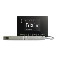
Displays: Two rows and function icons LCD display.
Alarm buzzer:
Built-in.
Incorporated sensors:
temperature and humidity (according to the
model)
Bluetooth Low Energy (according to the
model).
Working range incorporated temperature and humidity sensor:
0... 40 °C (32... 104 °F) 10... 70 % of relative humidity.
Communications ports:
1 INTRABUS port or RS-485 port with IN-
TRABUS or MODBUS communication protocol
(according to the model).
According to European R&TTE Declaration of Conformity this device can be used in the follow-
ing Countries: Austria, Belgium, Cyprus, Czech Republic, Denmark, Estonia, Finland, France,
Germany, Greece, Hungary, Ireland, Italy, Latvia, Lithuania, Luxembourg, Malta, Norway, Po-
land Portugal, Slovakia, Slovenia, Spain, Sweden, Switzerland, The Netherlands and The United
Kingdom.
N.B.
The device must be disposed of according to local regulations governing the collection
of electrical and electronic waste.
This document and the solutions contained therein are the intellectual property of EVCO and thus pro-
tected by the Italian Intellectual Property Rights Code (CPI). EVCO imposes an absolute ban on the full
or partial reproduction and disclosure of the content other than with the express approval of EVCO. The
customer (manufacturer, installer or end-user) assumes all responsibility for the configuration of the de-
vice.
EVCO accepts no liability for any possible errors in this document and reserves the right to make any
changes, at any time without prejudice to the essential functional and safety features of the equipment.
EVCO S.p.A.
Via Feltre 81, 32036 Sedico (BL) ITALY
Tel. 0437/8422 | Fax 0437/83648
email info@evco.it | web www.evco.it
 Loading...