Do you have a question about the Evco EVJ LCD and is the answer not in the manual?
Details available models, purchasing codes, and technical features of the devices.
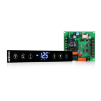
Overview of the EV3 MVC controller layout and its components.
Layout and component description for EVD MVC and EVD EXP controllers.
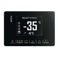
Layout and component description for the EV3K11 remote keypad.
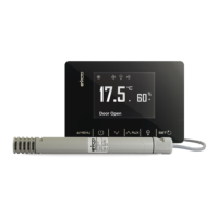
Layout and component description for the EVJ LCD remote keypad.
Dimensions and panel installation guidelines for the EV3 MVC controller.
Dimensions and DIN rail installation for EVD MVC/EXP controllers.
Dimensions and panel installation for the EV3K11 unit.
Dimensions and wall/box installation for the EVJ LCD remote keypad.
General safety and environmental precautions for device installation.
Explanation of the functions for each key on the controller interface.
Description of the controller's display elements and LED indicators.
Description of signalling LEDs for EVD MVC and EVD EXP controllers.
Wiring diagram and example for connecting the EV3 MVC controller.
Wiring diagram and example for connecting the EVD MVC controller.
Detailed description of all connectors for the EV3 MVC controller.
Detailed description of connectors for EVD MVC and EVD EXP.
Detailed description of connectors for the EV3K11 unit.
Detailed description of connectors for the EVJ LCD remote keypad.
Procedure for setting the termination resistor for RS-485 MODBUS line.
Important safety precautions for electrical connections of the devices.
Overview of the available menus and their access functions.
Detailed list and description of all configurable parameters.
Configuration options and types for digital and analogue inputs.
Configuration options for analogue outputs (0-10V, PWM, frequency, phase cutting).
Configuration of triac and open collector outputs.
Configuration options for digital outputs.
Details on INTRABUS and RS-485 serial port configurations.
Explanation of the incremental neutral zone regulation mechanism.
Options for selecting operating modes like hot/cold, manual, or timer.
How to activate free heating and free cooling functions.
Control of supply and return fans, including speed and post-ventilation.
Management of different types of recovery heat exchangers and defrosting.
Control of the mixing chamber damper for air exchange and comfort.
Temperature control algorithms using neutral zones and probes.
Compressor management, safety features, and coil types.
Maintaining constant fan speed for pressure or capacity control.
Controlling CO2 levels via damper and fan speed.
Managing room humidity for comfort in winter and summer cycles.
Limiting external air intake to maintain room temperature in extreme conditions.
Catalog of device alarms, their display codes, and descriptions.
Current operating status of the unit (ON, Stand-by, etc.).
Device's current operating mode (Comfort, Economy, Holiday, etc.).
Status of fan regulation settings and modes.
Current setpoint value for damper regulation.
Status of various coil functions and their operational parameters.
Information on defrost phases, timing, and safety parameters.
Operational status of compressor, fans, and system resources.
Current measured values from all available probes.
Current status of all digital inputs.
Current status of analogue and digital outputs.
Information on accessing different user levels via password.
Description of the RS-485/USB interface for set-up software.
Details on the drip protector for EV3 MVC and EV3K11.
Description of connection kits (CJAV39, CJAV38) for cabling devices.
Identifies the primary function of each device model.
Details on device construction and casing material.
Physical dimensions and mounting methods for each device.
Information on front protection rating and connection types.
Specifications for operating and storage temperature and humidity.
Device pollution status and regulatory compliance information.
Details on power supply requirements and voltage ratings.
Information on software structure, clock features, and input configurations.
Specifications for outputs, actions, and display types.
Details on communication ports and built-in sensors.
| Brand | Evco |
|---|---|
| Model | EVJ LCD |
| Category | Controller |
| Language | English |