LT-101A User’s Manual
Copyright © EVERFINE, Copy or spread without authorization is prohibited.
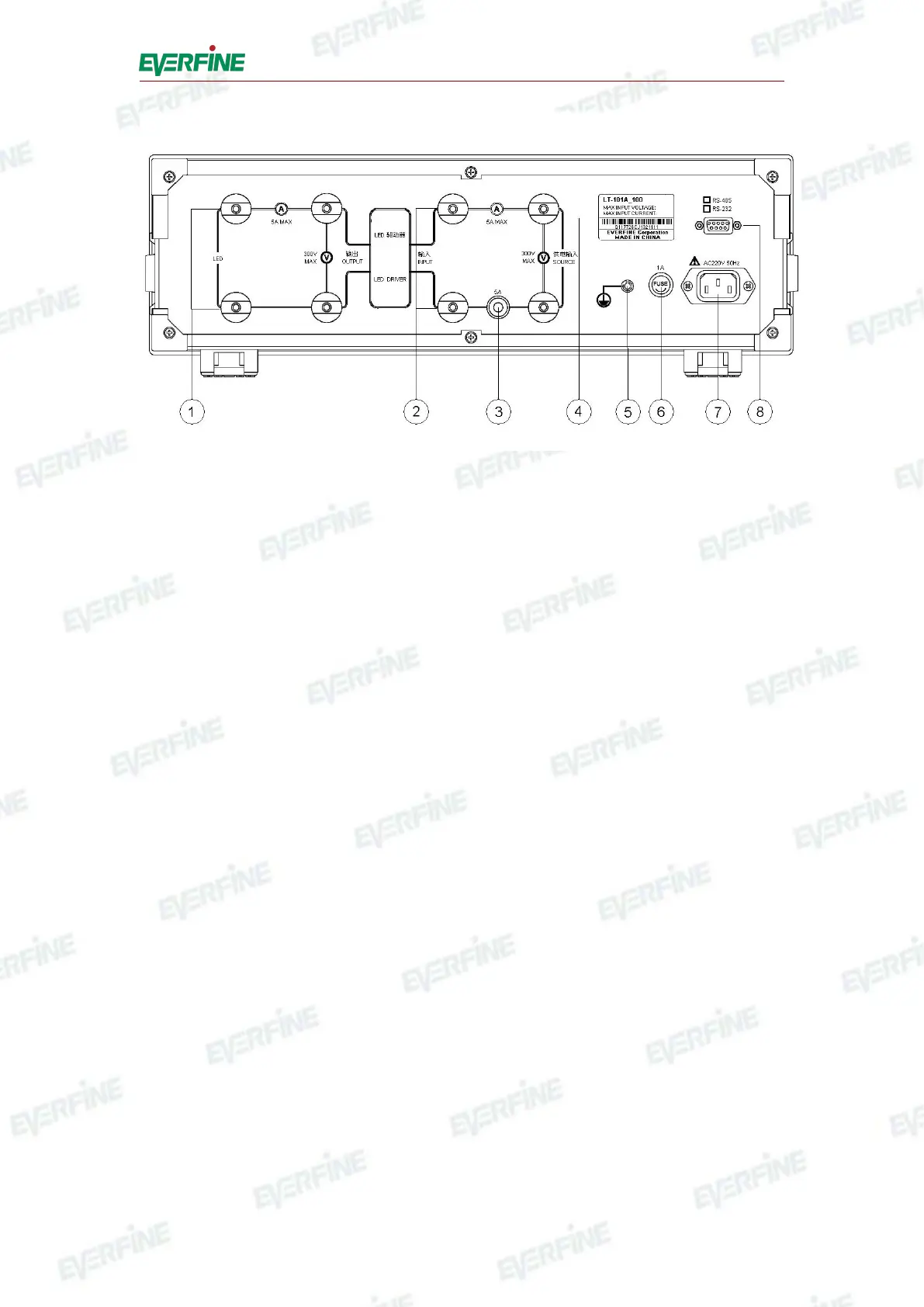
Fig.4.2 Rear Panel of LT-101A
○
1
Output measuring terminal: Output terminal of LED driver and input terminal of
LED load when measuring output characteristic of LED driver.
○
2
Input measuring terminal: Connect power supply and load when measuring input
characteristic of LED driver.
○
3
Fuse holder: There is a fuse for input current under test, with the specification
250V/8A and the dimensionφ5×20mm.
○
4
Nameplate: It is marked with type, ex-factory, maximum input voltage, maximum
input current, etc.
○
5
Grounding terminal: For the safe of the users, the instrument should be well
grounded.
○
6
Fuse holder: There is a fuse for the instrument inside it, with the specification
250V1A and dimensionφ5×20mm.
○
7
Power: Socket for the instrument, the rated voltage is AC 220V/50Hz or
220V/60Hz.
○
8
RS-232-C interface: To communicate with computer via this interface.