LT-101A User’s Manual
Copyright © EVERFINE, Copy or spread without authorization is prohibited. 15
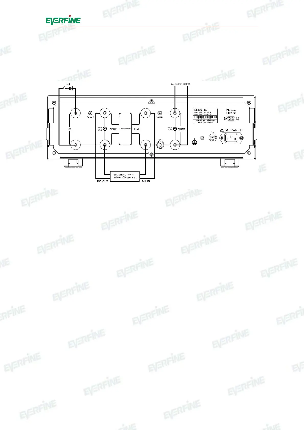
4.2 Measurement connections
Make sure that the power supply is in the range of the rated value, which is AC
220V.±22V, 50Hz/60Hz. The measurement connection is shown as Fig.4.3.
Fig.4.3 Measurement connections
To connect the measurement wires according to Fig.4.3.
Press power switch in front panel to turn on the instrument.
Please refer to Chapter 5 for the operation of setting and testing parameters.
If you need remote control, connect the RS232 interface (
○
8
of the Fig.4.2) in rear
panel with PC serial communicate interface, please refer to Chapter 6 for details.
When finishing the test, turn off the power supply for LED driver before turning off
the power switch on front panel, the instrument will stop working.
Note: The power supply for LED driver should be turned off before starting the
instrument.