LT-101A User’s Manual
Copyright © EVERFINE, Copy or spread without authorization is prohibited. 7
Chapter 2 Fundermentals
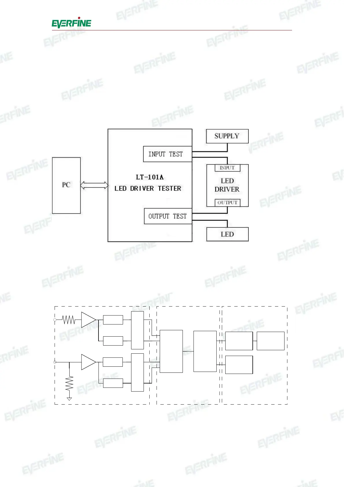
2.1 System structure of LT-101A
The system structure of LT-101A is shown in figure 2.1. The device can both work
independently and communicate with the computer testing system.
Fig.2.1 System structure of LT-101A
2.2 Schematic diagram of LT-101A
A/D
ISO.
ZERO
FPGA DSP
KEY&LED
CONTROLLER
RS-232-C
/RS-485
KEY&LED
A/D
ISO.
ZERO
INPUT
CPU INTERFACE
V
A
Fig.2.2 Schematic diagram of LT-101A
Schematic diagram of LT-101A is shown in figure 2.2, The LT-101A device can