LT-101A User’s Manual
Copyright © EVERFINE, Copy or spread without authorization is prohibited. 31
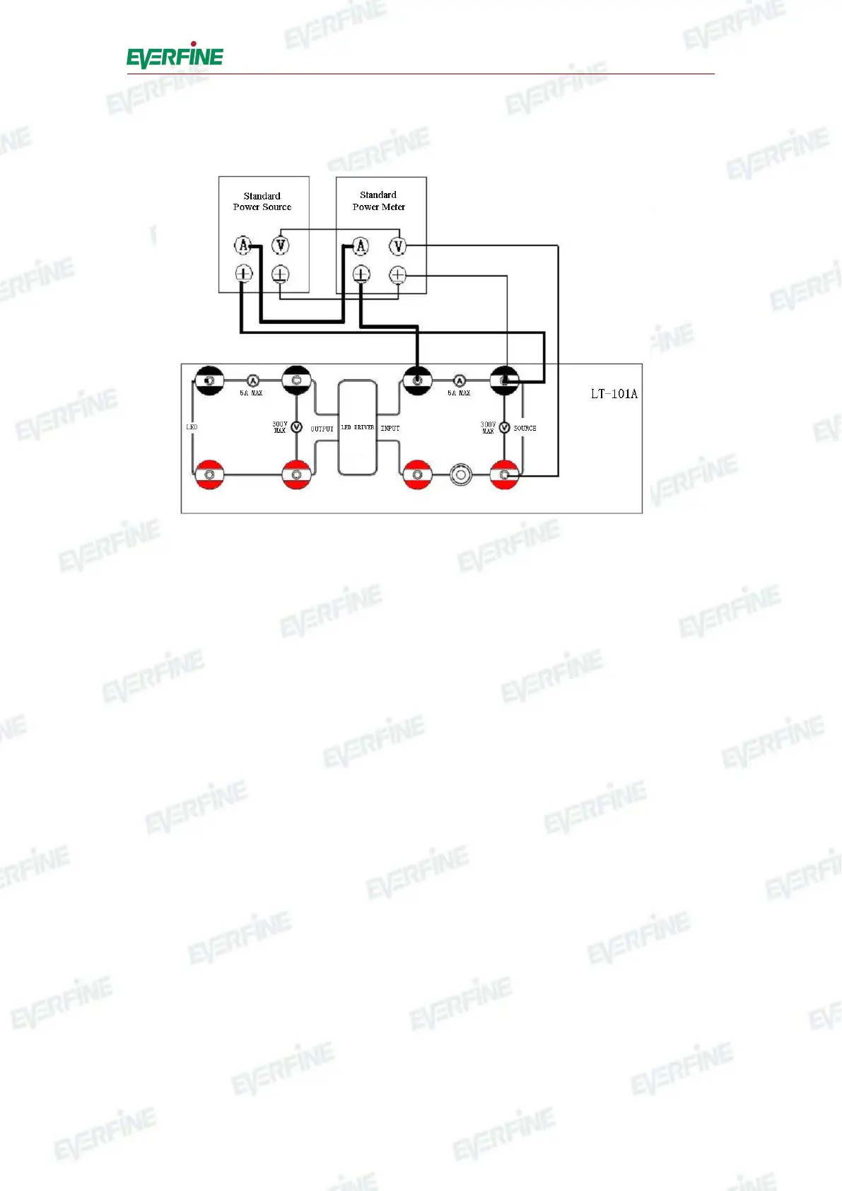
thin line shows voltage connection of the test channel. The connection for output test
channel refers to input channel.
Fig.7.1 Verification connection of input channel
(2) Verification of voltage, current and power
Adjust the power source to output voltage and current, record the reading value of
the standard power meter and the measurement value by LT-101A.
Calculate the measurement error of voltage: ΔU=Ux-Us
Calculate the measurement error of current: ΔI = Ix-Is
Calculate the measurement error of active power: ΔP = Px-Ps
where,
ΔU is the measurement error of RMS value of voltage measured by LT-101A;
Ux is the RMS value of voltage measured by LT-101A;
Us is the RMS value of voltage measured by the standard power meter;
ΔI is the measurement error of RMS value of current measured by LT-101A;
Ix is the RMS value of current measured by LT-101A;
Is is the RMS value of current measured by the standard power meter;
ΔP is the measurement error of RMS value of active power measured by
LT-101A;
Px is the RMS value of active power measured by LT-101A;