- 5
Assembly Instructions
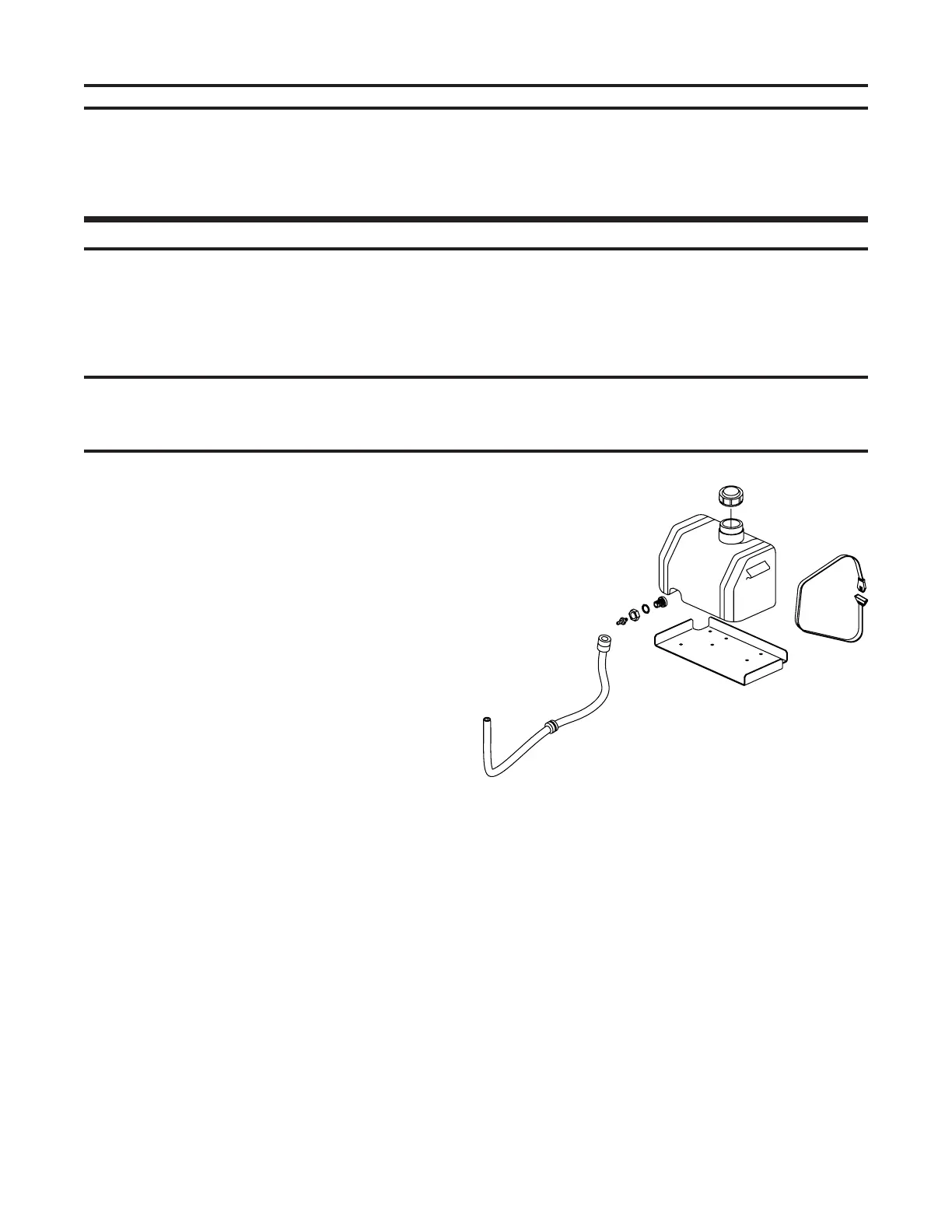
Fig. 1
6. Using the remaining 4 - 3/8” X 1” bolts and
the 4 – 3/8” nyloc nuts, bolt the upper handle
into position. (Remember that there are 3
– height settings for the handle for operator
comfort.) Route the wiring harness along
the handle, plugging it into the blade control
switch, using the screws to attach the
harness to the Operator Presence Control
switch. There is not a specifi c color for
hooking up the harness.
SPECIFICATIONS
Belt Tension Guide
Defl ection Measured With 12 lbs. of Force
Belt
Engine to Deck
Transmission Belt
Right Blade Drive Belt
Wheel Drive
Inch Defl ection
1/2”
1/2”
1/2”
(48”,52”, And 60” only)
1/2”
How to Adjust
Turnbuckle at Idler
Sliding Idler
Threaded Rod to Idler
Self-Adjusting
1. Remove inner parts box and handle from
crate. Remove outside frame work so that
the mower is setting on the pallet.
2. On a 36” mower, use 3 – 5/16” X 1 3/4” bolts
and 3 – 5/16” whizlocks and bolt the bumper
into place. (On the 48” there are 4 - bumper
bolts required.)The whizlocks should go to
the inside of the deck. When assembling
a 48” mower, make sure that the bumper
is fl ush with the deck on both ends of the
bumper.
3. Using 6 – 3/8” X 1” bolts (3 – used for each
caster) and 6 – 3/8” whizlock nuts, bolt the
casters into place. Position whizlock nuts to
the inside of the deck.
4. Using 2 – 5/16” X 1” bolts with 2 – 5/16”
fl at washers and 2 – 15/16” nyloc nuts,
take the shifter lever with grip and bolt onto
the top side of the shifter bracket on the
transmission. Place the 5/16” fl at washers
on the slotted hole side of the shifter bracket
under the 5/16” nut. Position the shift lever
so that it slides freely along the top side
of the shifter plate but still hits the stop for
reverse.
5. Mount the gas tank using the 2 – nylon hold
down straps, pulling tension on the buckles
until secure. Attach the quick coupler, on the
end of the fuel line, to the bottom of the tank.
(See Fig. 1)
SPECIFICATIONS/ASSEMBLY INSTRUCTIONS