Do you have a question about the evertz 7825DSK2-LG-HD and is the answer not in the manual?
Provides a concise overview of the 7825DSK2-LG-HD and 7825DSK2-LG-3G Dual Downstream Keyer and Logo Inserter.
Explains the manual's organization, structure, and how to navigate its content effectively.
Defines technical terms and acronyms used throughout the manual for clarity and understanding.
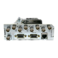
Details the physical connectors and ports located on the rear panel of the 7825DSK2-LG(-HD)(-3G) modules.
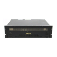
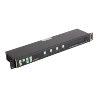
Describes the procedure and specifications for physically mounting the remote control panel into a rack.
Outlines the electrical power specifications, including voltage, supply, and cord requirements for the unit.
Provides instructions on how to connect the remote control panel to the keyer unit using serial communication.
Explains how to connect video sources and reference signals to the unit's input and output connectors.
Details how to connect a linear time code source for time information and logo insertion.
Guides the user on establishing an Ethernet network connection for firmware upgrades and file transfers.
Describes how to connect general-purpose inputs and outputs (GPIO) for control and status feedback.
Explains the connection procedure for the optional temperature probe used for temperature logos.
Lists the tools and methods available for configuring the module's features and parameters.
Details the process of configuring the module's network settings via the card edge serial port using a terminal program.
Explains how to integrate and control upstream routers with the downstream keyer unit.
Describes the function of the LOCAL STATUS LED, indicating module health and power fault conditions.
Explains the FPGA STATUS Green LED, which indicates proper module boot-up status.
Describes the function of the four CARD ACTIVITY LEDs, which indicate card activity during operation.
Introduces VistaLINK®, Evertz's remote monitoring and configuration platform using SNMP.
Covers settings related to video connections, including standard, reference type, and output timing.
Details parameters for setting and displaying the unit's real-time clock, UTC, and local time.
Allows viewing and configuring network settings such as IP address, subnet mask, and gateway.
Provides access to port configuration, firmware information, AFD, and MCP control settings.
Used to configure the downstream keyer functions, including key type, gain, and thresholds for both DSK layers.
Configures the black overlay matte attributes, including aspect ratio and position for letterbox effects.
Enables configuration of General Purpose Inputs and Outputs for control and triggering functions.
Configures parameters for logos that display the current local temperature, including source and format.
Allows configuration of transition types, rates, pause modes, and program bus changes between video sources.
Configures parameters for Emergency Alert System (EAS) messages, including crawl display settings.
Manages user presets for storing and recalling configurations of matte, transition, and DSK settings.
Controls parameters for individual logos and media items, including positioning, fading, and animation.
Manages audio parameters for embedded audio, including gain, ducking, and source selection.
Lists various playlist commands and provides a description of their respective functions for script building.
Describes how to access and configure audio settings and METAR data via an HTML setup page.
Explains the initial Index page accessed via the HTML setup, providing links to other configuration sections.
Details the requirements and configuration for playing WAV files as audio clips through the unit.
Covers configuration for acquiring meteorological data (METAR) for temperature logos from airports.
Allows manual setting of the system's date and time through the HTML setup page.
Configures IP addresses for SNMP Trap destinations to receive alerts from the unit.
Configures proxy and DNS server settings for Internet access, potentially needed for data feeds.
Provides functionality to remotely reboot the 7825DSK2-LG(-HD)(-3G) unit via the HTML interface.
Lists the detailed technical specifications for video input/output, reference, LTC, control, and GPIO interfaces.
Details the standards, number of inputs, connector types, equalization, and return loss for serial digital video input.
Specifies the standards, number of outputs, connectors, signal levels, and timing characteristics for serial digital video output.
Describes the type, connectors, termination, and frame genlock settings for video reference signals.
Details the standard, frame rate, connectors, and level for the LTC reader on the breakout cable.
Specifies the port type, protocol, and baud rate for the remote panel control interface.
Lists the number of inputs/outputs, type, connector, and signal level for the GPIO interface.
Provides electrical specifications including voltage, power consumption, and EMI/RFI compliance.
Outlines the physical dimensions or slot requirements for the unit within its frame.
Introduces the firmware upgrade process, its necessity, and the recommended methods.
Details the recommended firmware upgrade procedure using the Overture application via Ethernet.
Explains the two-step process for upgrading firmware using a terminal program and serial connection.
Explains how to create and use GPI script files for controlling unit functions via GPI triggers.
Defines the syntax for scripting objects, types, and properties used in GPI scripting.
Provides example GPI scripts for configuring audio and mapping sources using SAP programming.
Illustrates GPI scripts to invoke a trouble slide or fade out media and audio clips.
| Brand | evertz |
|---|---|
| Model | 7825DSK2-LG-HD |
| Category | Computer Hardware |
| Language | English |