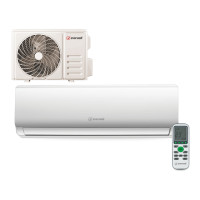
Do you have a question about the Everwell MKTH1223E-16 and is the answer not in the manual?
Covers critical safety precautions for installation and maintenance, including electrical and general safety guidelines.
Details operational safety, static electricity precautions, installation safety, and cautions for refrigerant leak detection.
Covers inspection of the maintenance environment, equipment, air conditioner, leak inspection, and general safety principles.
Details the process of vacuuming the refrigerant circuit and performing leakage detection tests.
Describes the final test procedures, including client approval and checking unit operation in different modes.
Provides a flowchart for diagnosing and resolving IDU & ODU communication failures.
Flowchart for troubleshooting IDU room and coil temperature sensor failures.
Flowchart for diagnosing cooling system abnormalities, often related to insufficient gas.
Flowchart for troubleshooting IDU ventilation issues, specifically for PG and DC fan motors.
Flowchart for diagnosing ODU coil, ambient, or discharge temperature sensor failures.
Flowchart for diagnosing ODU IPM or compressor drive faults, often related to protection modes.
Flowchart for troubleshooting ODU DC fan motor failures.
Flowchart for diagnosing ODU voltage test sensor failures.
Flowchart for diagnosing IPM protection issues, including compressor and fan motor checks.
Flowchart for diagnosing over/under voltage protection issues on the power supply and busbar.
Flowchart for diagnosing over current protection, checking fan motor, filters, and condensers.
Flowchart for ODU discharge temperature overheating protection, checking location, ventilation, and components.
Flowchart for sub-cooling protection in cooling/dry mode, checking filters, air inlet, and fan motor.
Flowchart for cooling mode overheating protection, checking fan motor, sensors, and PCB.
Flowchart for heating mode overheating protection, checking fan motor, sensors, and PCB.
Flowchart for outdoor over/under temperature protection, checking ambient conditions and ventilation.
Flowchart for compressor drive protection, checking wiring, startup, and pressure balance.
Flowchart for cooling system gas flow abnormal protection, checking valves and IPT sensor.
Flowchart for PFC (Overcurrent) protection, checking power supply and unit restart.
| Brand | Everwell |
|---|---|
| Model | MKTH1223E-16 |
| Category | Air Conditioner |
| Language | English |


 Loading...