02 03
STEP STEP
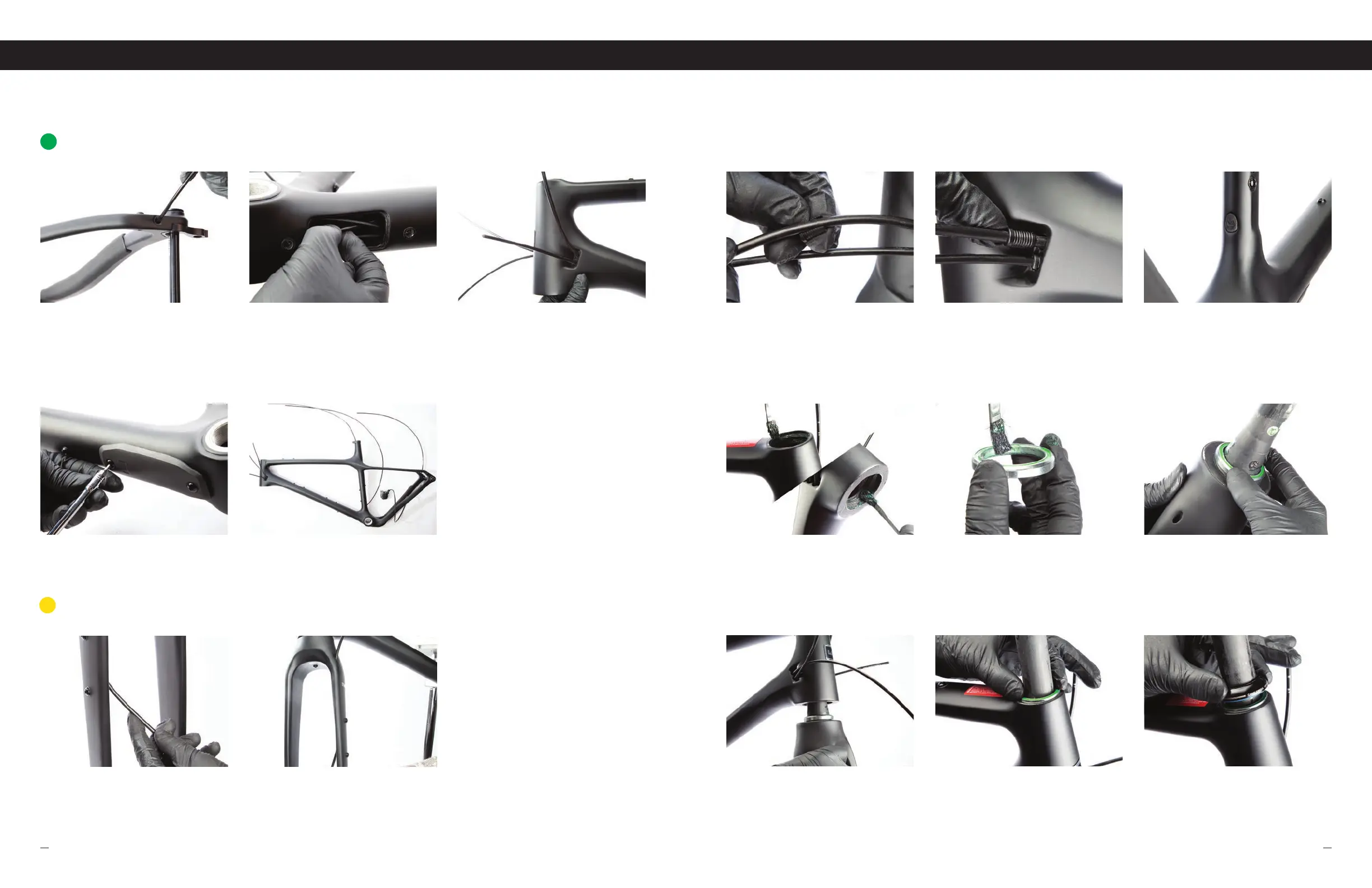
Using the down tube window, route rer derilleur housing under
internl bottom brcket nd up down tube.
Using finger to guide rer derilleur housing from inside the hed
tube, exit cble through the bottom left port.
With 3mm hex key, rettch the down tube cp (DWNT).
04
STEP
05
STEP
Now tht ll cble housing nd brke lines hve been run, it's time
to build the rest of your bike. NOTE: Dropper post housing length is
relative to your personal saddle height. All housing nd brke line
length need to be djusted ppropritely to cyour custom bike fit.
FIT CLIPS, PLUGS AND CAPS
01 02 03
STEP STEP STEP
Fit lips come in 2 sizes, 5mm nd 4mm. Sizes ccommodte
the outer dimeter of the cble housing nd the brke lines. Also
included re Solid Port Plugs nd Rer Hnger p. Refer to
the exploded view drwing for plcement nd loction.
Once cbles nd lines re if finl position insert Fit lips nd Port
Plugs in to ports where needed.
Exmple of Rer Hnger p instlled on the bottom of set tube.
HOUSING & BRAKE LINE ROUTING
11
ASSEMBLING YOUR FRAME
The following pges re ment to help you ssemble the min components specific to this frme. Plese refer to the
component mnufcturer's ssembly specifictions nd instructions for further ssistnce if necessry.
FORK INSTALL
01 02 03
STEP STEP STEP
Lightly pply grese to upper nd lower integrted hedset cups
inside hed tube.
Lightly pply grese to integrted crown rce locted on fork
crown.
nstll bering over steer tube nd onto fork crown rce. Mke
sure bering is in correct orienttion nd is seted correctly onto
the integrted fork crown rce.
04 05 06
STEP STEP STEP
With bering instlled onto fork, insert fork into bottom hed
tube opening. Ensure bottom bering is correctly seted in lower
integrted hedset cup.
With fork instlled into frme, instll upper bering onto steerer
tube nd into upper integrted hedset up. Ensure upper bering
is in correct orienttion.
nstll top cover ssembly onto steerer tube nd into upper
bering. Ensure top cover ssembly is in the correct orienttion.
NOTE: Installing spacers, stem and cutting steer tube to size will
vary with individual bike setup.
FRAME ASSEMBLY
12
FRONT FORK BRAKE LINE
01 02
STEP STEP
After ssembling fork (s shown in next section) guide front
brke line up through inside port.
uide brke line up through the top port leving enough line to
cut to custom length.
E
REAR DERAILLEUR
D
nstll rer derilleur housing into bck port of the right (drive side).
01
STEP
INSTALLATION CONTINUED
FIND OUT MORE AT EVIL-BIKES.COMBLEED BLACK, RIDE EVIL
 Loading...