16 17
www.evolutionpowertools.com www.evolutionpowertools.com
EN
ES
FR
NL
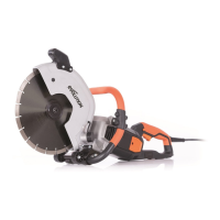
• Pressthearborlockbuttontolockthearbor.(Fig. 4)
• Unscrewthearborboltusingthewrench.
Note: The arbor bolt has a right hand thread.
• Removethesawblade,leavingtheinnerbladeflangeinits
service position.
• Thoroughlycleaninnerandouterbladedriveflangesand
blade mounting surface before installing a new blade.
• Ensurethatthedirectionofrotationarrowsprintedonthe
blade match the direction of rotation arrow found on the
chip collector. (Fig. 5)
• Reinstalltheouterdriveflangeandthearborbolt.
• Engagethearborlockandtightenthearborboltsecurely
using the wrench.
• Replacethechipcollectorandsecurelytightenthethumbscrew.
• Checkthatthearborlockisfullyreleasedbymanually
rotating the blade.
• Replacethewrenchandsecureitintothebaseplateusing
the thumb screw.
• Replacetheparalleledgeguideifrequired.
Parallel Edge Guide
A parallel guide (for help when rip cutting) can be fitted to the
base plate of the machine. The guide’s arms should be inserted
into the rectangular slots in the turned up edges of the base
plate, and slid under the locking thumb screws. (Fig. 6)
Note: The parallel edge guide can be fitted to either side of
the base plate and should only be fitted and adjusted with the
machine disconnected from the power supply.
Adjust the parallel edge guide so that it is at the required
distance from the blade and tighten the two thumb screws.
Check that the parallel edge guide is parallel to the saw blade.
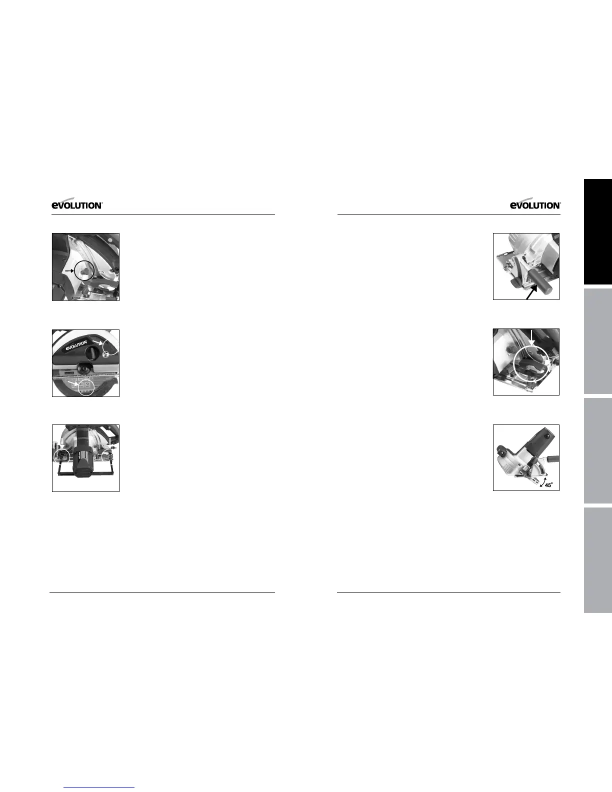
Auxiliary Handle (Fig. 7)
The auxiliary handle (supplied) can be screwed into the boss
found on the Bevel Locking Quadrant.
This handle will provide the operator with a convenient position
for their left (or right) hand during cutting operations.
Adjustment of the Cutting Depth
Release the lever lock (Fig. 8) to adjust to the required cutting
depth. Adjust the cutting depth to the thickness of the
workpiece. Less than a full tooth of the blade teeth should be
visible below the workpiece.
Note: Always check to see if there are any obstructions below the
work surface that could influence the setting of the cutting depth.
Tighten the lever lock securely to lock in the required position.
Adjustment of the Cutting Angle
• Loosenthebevellockingscrewfoundatthefrontofthesaw.
• Loosentherearbevellockingscrewfoundattherearofthe
machine’s base plate.
• Tiltthebladetotherequiredangle(Fig. 9)
• Tightenbothbevellockingscrewssecurely.
Note: An angle scale (0 – 45
0
) is incorporated into the bevel
locking quadrant to aid setting.
OPERATING ADVICE
Carry out routine safety checks each time you use the machine.
Check that all safety guards are operating correctly, and that all
adjustment handles/screws are tightened securely.
Check that the blade is secure and installed correctly. Also check
that it is the correct blade for the material being cut.
Check the integrity of the power cord.
Always clamp the workpiece to a rigid support such as a bench
or saw horse whenever possible.
Fig. 5
Fig. 6
Fig. 4
Fig. 7
Fig. 8
Fig. 9