12 13
www.evolutionpowertools.com www.evolutionpowertools.com
6. FOOTPLATE ANGLE ADJUSTMENT
Note: The footplate is factory set and adjusted so that the blade
cuts at 90
0
to the footplate.
The footplate may be tilted to an angle of up to 45
0
to either side with
positive location stops at 15
0
, 30
0
and 45
0
.
To adjust the footplate:
WARNING: Disconnect the jigsaw from the power supply before
attempting to adjust the footplate.
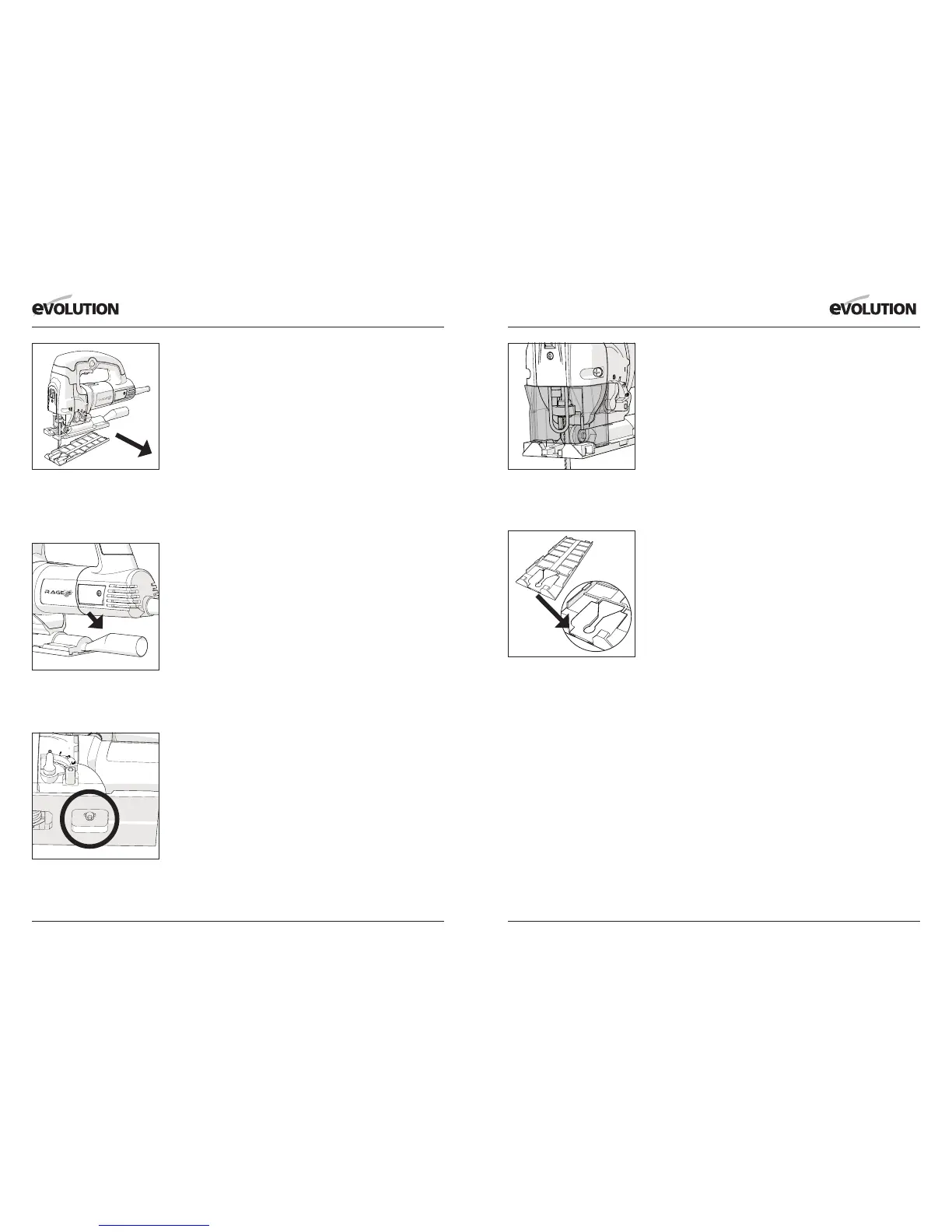
• Unclip the plastic footplate shoe and store safely for future
installation. (Fig. 6)
• Withdraw the Dust Extraction Adaptor tube, if tted, and store
safely for future installation. (Fig. 7)
• Loosen the socket headed screw that holds the footplate to the
machine. (Fig. 8)
• Tilt the footplate to the desired angle. To engage one of the
positive stops it will be necessary to slide the footplate backwards
or forwards depending upon the stop required.
• Tighten the socket-headed screw carefully so as not to damage
the threads.
• Re-install the Dust Extraction Adaptor tube.
• Refit the plastic footplate shoe ensuring that all six (6)
securing lugs (2 to the front of the footplate and 2 either side)
are correctly seated.
Note: The positive location stops are intended as a guide only. For
accurate setting of the footplate we recommend the use of a vernier
angle gauge (not supplied).
Fig 6
View of footplate shoe being
unclipped and removed from
footplate.
Fig 7
View of Adaptor tube in service
position.
Fig 8
Close up view of socket headed
screw.
7. CHIP GUARDS
Two (2) plastic chip guards are provided. The Front Chip Guard
should always be tted and the Footplate Chip Guard can be tted
to the machine as and when required.
To t the Front Chip Guard:
• Ensure that the machine is disconnected from the power supply
• The front guard (Fig. 9) clips over the front of the machine, below
the laser guide and in front of the steel blade guard.
Note: This guard is precisely engineered and designed to just clip
into place. There is sufcient ‘spring’ in the design to allow the guard
to be carefully positioned into its service position. The operator
should use care and ensure that the guard is not ‘forced’ into place
with the attendant risk of damage to the guard. Seat the guard
carefully in its service position.
The Footplate Chip Guard (Fig. 10) can be useful when cutting long
straight lines. The use of this guard will help prevent the sawblade
from swinging during a cut.
To t the Footplate Chip Guard:
• Ensure that the machine is disconnected from the power supply.
• Unclip the plastic Footplate Shoe from the Footplate.
• Clip the Footplate Chip Guard into the inside of the Footplate
Shoe with the ‘Vee’ pointing towards the rear of the shoe, and the
raised platform positioned within the throat of the shoe. Ensure
positive location within the shoe. The guard should lie ‘ush’ with
both surfaces of the shoe.
• Carefully replace the Footplate Shoe with the attached Chip
Guard onto the Footplate.
Fig 10
Close up view of Footplate
Guard in service position before
installation of footplate shoe.
Fig 9
Close up view of Front
Guard in service position.