11
Evolution UC-33e
MIDI In/Out & MIDI Messages Explained
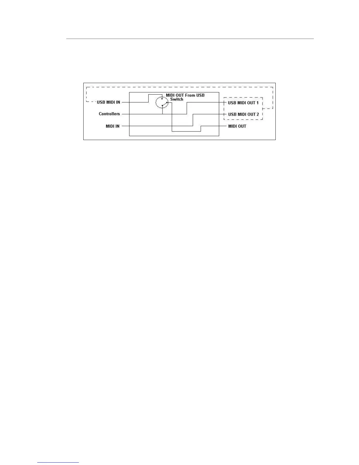
MIDI In & MIDI Out Signal Flow Diagram
The MIDI IN & MIDI OUT ports have different uses depending on how you intend to connect and power the UC-33. The diagram below shows the
different routing options.
About The MIDI In Port
The MIDI in plug can be used to interface another MIDI device to your PC, via the USB port. Data received from this device will be transmitted via the
UC-33 to the PC. This is achieved using a second USB MIDI out. So, when you select the MIDI devices section of your sequencer you will see two UC-33
USB MIDI Ins. The first of these is used to receive the UC-33 controller data, the second is used to receive data from the other device connected to the
UC-33’s MIDI IN plug. So, the UC-33 is acting as a MIDI-to- USB interface for the other MIDI device.
About The MIDI Out Port
The UC-33 can of course also interface with other MIDI devices. By default (I.e. when you switch the unit on), all controller data is sent out via the MIDI
output as well as the USB out.
If you want the MIDI output to act like a traditional USB-to-MIDI interface, just press the two buttons (SELECT and ASSIGN) that activate the MIDI
OUT from USB mode.
If you are using a host application which can pick up multiple input drivers, you will be able to use the UC-33’s MIDI input and the UC-33 surface to
record MIDI data and send the whole lot out of the UC-33’s MIDI output.
Important note: The UC-33 is not a MIDI THRU device and as such, MIDI data received at the UC-33’s MIDI IN plug can never be sent directly to the UC-33’s
MIDI OUT plug. However, if the UC-33 is connected via USB to a computer, data received at the MIDI IN can be transmitted to the MIDI OUT plug, since the data
is sent to the computer, and received back from the computer. MIDI OUT FROM USB mode must be engaged for this to occur.
Program & Bank Changes Explained
The original GM MIDI specification catered for only 128 voices, numbered from 0-127. It is possible to access a different voice by sending a program
change.
In order to expand on the GM set of voices, Bank changes were devised. Each bank contains 128 patches, which can be accessed using a program change.
There are 16,384 banks available, accessible by sending a 14-bit Bank change message. The first 7 bits of this message are sent in a single byte known as
the Bank LSB. The last 7 bits are specified by another byte known as the Bank MSB. The BANK LSB is the most commonly used This allows for 128 bank
changes, and often there is no need to send a Bank MSB.
You will find almost all MIDI devices respond to the program change, but some that do not conform to the GM set of voices use the program change
message for other purposes. Many VST instruments have adopted this approach, allowing you to use a program change to change the instrument patch.
The FM7 by Native Instruments is a good example of this.
Bank changes are more rarely used, although they do exist. Bank changes are useful in manufacturer’s extensions to the MIDI specification, such as
Roland’s GS specification and Yamaha’s XG specification. Both of these require you to specify a Bank change, in order to access the extra voices and
effects that these specifications provide.
Sending Program, Bank LSB and Bank MSB data is made simple using the UC-33. Simply press the PROGRAM, DATA LSB or DATA MSB button and enter
the program or bank change you wish to send.
4