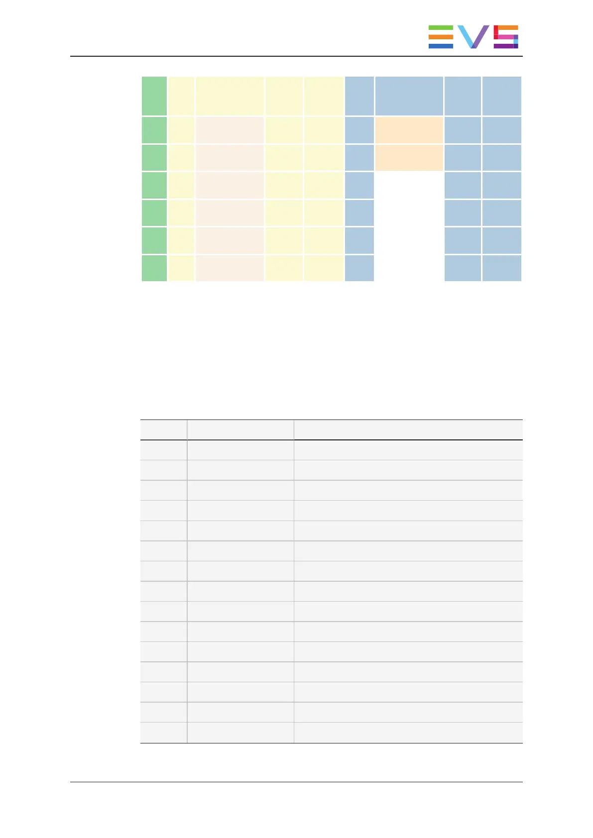
Rec.
PGM
outp
#
PGM DB-25
connector
name
PGM
outp.
pins
PGM
cmd.
mask
PRV
outp.
#
PRV DB-25
connector
name
PRV
outp.
pins
PRV
cmd.
mask
Cam
1
1 1-4 24-25 0001 7 5-8 18-19 0040
Cam
2
2 1-4 21-22 0002 8 5-8 15-16 0080
Cam
3
3 1-4 18-19 0003 9 9-12 24-25 0100
Cam
4
4 1-4 15-16 0004 10 9-12 21-22 0200
Cam
5
5 5-8 24-25 0005 11 9-12 18-19 0400
Cam
6
6 5-8 21-22 0006 12 9-12 15-16 0800
I/O Output: Reed relays, electrically isolated from each other
Electrical power: 48 Volt DC
Switching capacity max. 15 watts
Switching current typ. 500mA, max. 1 Amp
Contact resistance max. 150 mOhm
Detailed pin assignments of the first output 1-4 DB-25 (inputs are not used) are shown in
the table below.
PIN Designation Description
1 OPTO IN 4 - Input 4 (-)
2 OPTO IN 4 + Input 4 (+)
3 V_OUT1+ +5V, max. 100 mA load, short-circuit proof
4 OPTO IN 3 - Input 3 (-)
5 OPTO IN 3 + Input 3 (+)
6 V_OUT1 + +5V, max. 100 mA load, short-circuit proof
7 OPTO IN 2 - Input 2 (-)
8 OPTO IN 2 + Input 2 (+)
9 V_OUT1 + +5V, max. 100 mA load, short-circuit proof
10 OPTO IN 1 - Input 1 (-)
11 OPTO IN 1 + Input 1 (+)
12 V_OUT1 + +5V, max. 100 mA load, short-circuit proof
13 N.C. Not assigned
14 V_OUT1 - 0 Volt
15 RELAY OUT 4 b Output 4 b
INSTALLATION AND CONFIGURATION MANUAL X-One 1.7
4. Cabling 11