Do you have a question about the EXPERT GRILL XG11-362-071-230-02 and is the answer not in the manual?
| Brand | EXPERT GRILL |
|---|---|
| Model | XG11-362-071-230-02 |
| Category | Grill |
| Language | English |
Long metal rod with multiple pre-drilled holes.
Long metal rod with offset pre-drilled holes.
Vertical support bracket with mounting holes.
Long metal rod with pre-drilled holes and bracket attachment points.
Long metal rod with pre-drilled holes and offset bracket points.
Vertical support bracket with offset mounting holes.
Long, thin metal rod.
Bracket assembly with 'L' marking, featuring multiple attachment points.
Bracket assembly with 'R' marking and mounting holes.
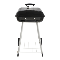
Large, flat panel, likely a side or back panel.
Large, flat panel with branded logo and textured surface.
Two wheels, designed for mobility.
Two conical feet, possibly for leveling or stability.
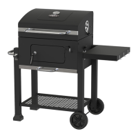
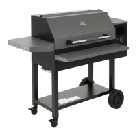
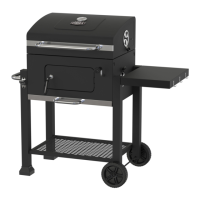
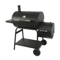
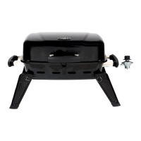
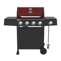
Main grill body, showing burners and control panel area.
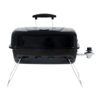
Curved metal shield or cover, possibly for heat deflection.
Rectangular metal cover, likely for a side shelf or compartment.
Curved gas hose with regulator and connection fitting.
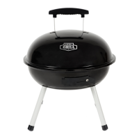
Round metal grate, possibly for a side burner.
Five conical caps, likely burner covers or igniter protectors.
Four angled metal heat shields or baffles.
Two large, rectangular cooking grates.
Two smaller, rectangular warming grates.
Wire frame component, possibly for supporting grates.
Single straight wire component, likely a support or bracket.
Wire frame component, possibly for grate support.
Shaped metal component, likely a drip pan or heat shield.
Wire frame component, possibly for securing items.
Rectangular metal drip pan with handle.
Illustration of basic tools required for assembly, including screwdrivers.
Detailed list of screws, washers, and nuts with identification labels (A-E).
Assemble the main frame structure using parts 1, 2, 3, 4, 5, and 6.
Join the two assembled frame sections using part 7.
Attach the 'L' and 'R' marked brackets (parts 8 and 9) to the frame.
Secure the large panel (part 10) to the assembled frame.
Install the wheels (part 12) and feet (part 13) onto the base.
Attach the large branded panel (part 11) to the side of the grill.
Place the main grill body (part 14) onto the assembled base structure.
Fasten the main grill body to the base using hardware.
Install the side heat shields (parts 15 and 20) onto the grill body.
Attach the side cover panel (part 16) to the grill structure.
Attach another side cover panel (part 16) to the opposite side.
Connect the gas control module to the main grill body.
Install the gas tube assembly (part 17) into the grill.
Connect the gas lines to the burners and side burner.
Complete the gas line connections to the main burners.
Place the side burner grate (part 18) onto its support.
Attach igniter caps (part 19) to the burner tubes.
Place the heat shields (part 20) inside the main grill.
Insert the main cooking grates (part 21) into the grill.
Place the warming grates (part 22) above the main grates.
Secure the grate support wires (parts 23 and 24) to the grill.
Attach another grate support wire (part 24) to the grill structure.
Attach the drip pan support wire (part 25) to the grill.
Install the drip pan (part 26) and its support.
Place the drip pan (part 26) and the tray (part 28) into the grill.
Connect the regulator hose to the propane tank.
Connect the gas regulator to the grill's gas inlet.