Model 380363 Version 2.0 July 2005
4
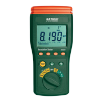
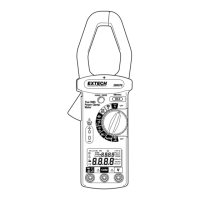
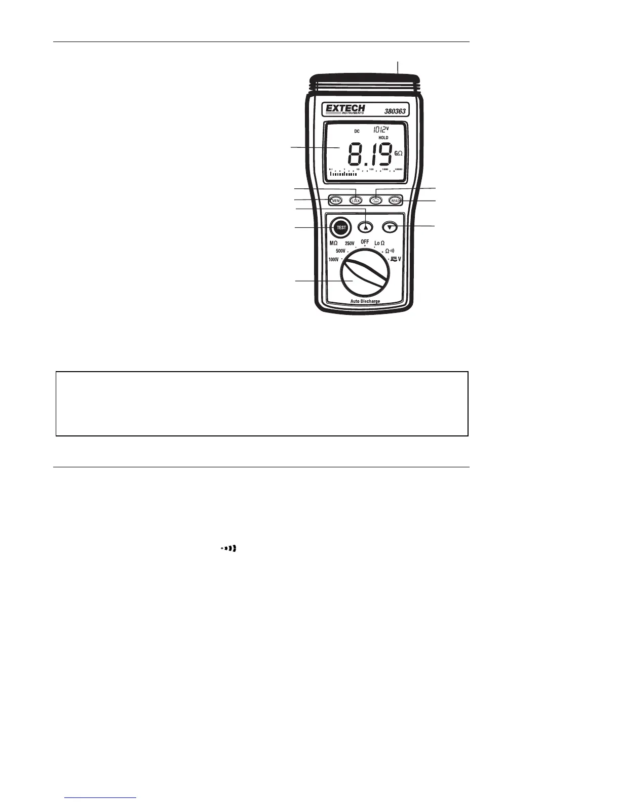
Meter Description
1. LCD Display
2. LOCK button
3. MEMORY control button
4. UP arrow key
5. TEST button
6. Rotary switch
7. DOWN arrow key
8. READ memory button
9. ZERO adjust button
10. Input terminals
The tilt stand and battery compartment are
located at the rear of the instrument
Operation
Connecting Test Leads
For all measurements connect the red test lead to the VΩ input terminal and the black test
lead to the COM input terminal.
Test Lead Check
1. Set the rotary switch to the Ω range.
2. Touch the test lead tips together.
3. Resistance should read less than 0.5Ω and the audio tone should sound.
4. With the leads not touching, the display should read OL indicating over-range.
5. Readings displayed other than the readings described above are evidence of a
problem and the test leads must be replaced before using the meter. Failure to do so
could result in damage to equipment and electrical shock. If replacing the test leads
does not solve the problem, return the instrument for repair.
Warning
Ensure that the circuit under test does not include components that can be damaged by 1000VDC; such
devices include power factor correction capacitors, low voltage mineral insulated cables, electronic light
dimmers, and ballasts/starters for fluorescent lamps.
1
2
3
4
5
6
7
8
9
10