6 MG310-en-GB_V1.0 12/15
INSUL ATIONRESISTANCEMEASUREMENTS
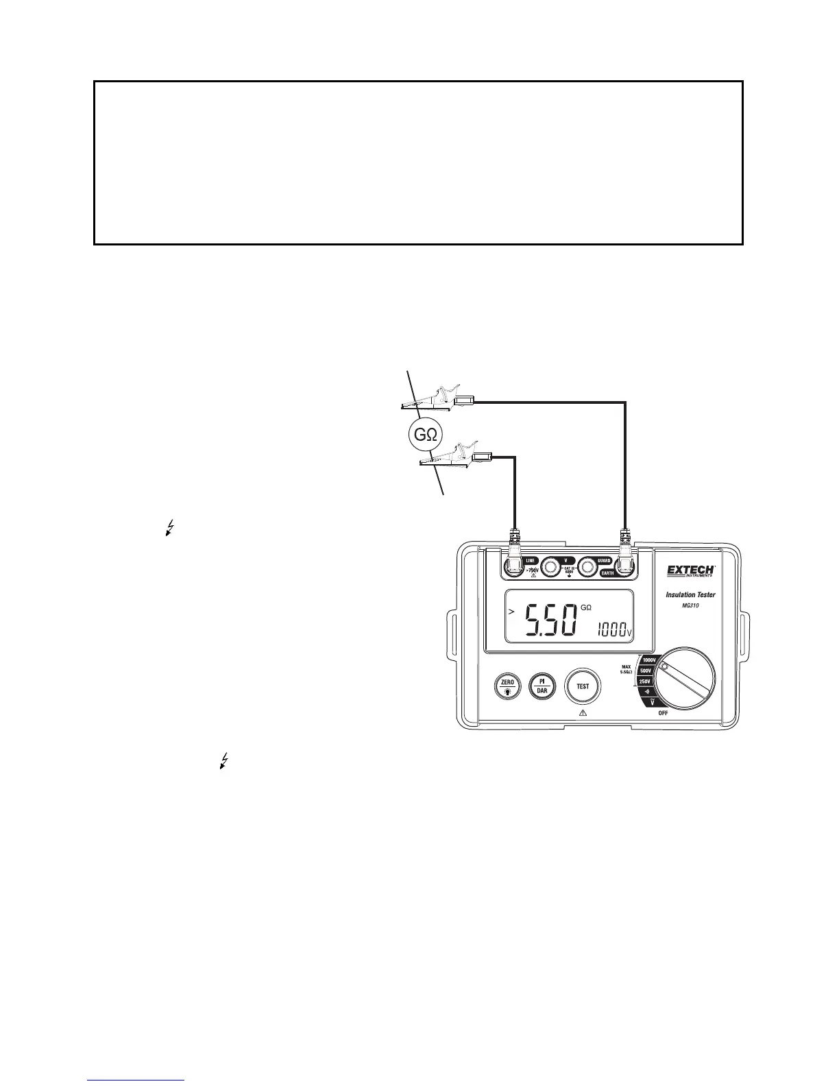
1. Selectthedesiredtestvoltageusingtherotaryfunctionswitch.Selectthe250V,500V,or
1000Vswitchpositionforthecorrespondingoutputtestvoltage.
2. Connecttheredtestleadtothemeter’sLINE(4)jackandtheblacktestleadtotheEARTH
(1)jack.Connectthe
probeendofthetestleadstothe circuitundertest.
3. PresstheTESTbuttontotest.The
buttonwillself‐lockandthebutton
lampwilllight.
Note:Ifthecircuitundertestislive
andhasavoltagepotential(AC/DC)
over30V,themeterwillnottest
(the
displaywillshowthe“>”iconand
the
symbolwillflash;thebuzzer
willalsosound).Ifthecircuitunder
testisnotliveorifitsvoltageisless
than30V,themeterwillbegin
applyinghigh‐voltagetothecircuit
undertest.
4. Theprimarydisplaywillshowthe
insulationresistanceinMΩ
(megaohms)orGΩ
(gigaohms).
5. Thetestvoltage(VDC)valuewillbe
indicatedintheright‐mostauxiliary
display,the
symbolwillflashandthecautionbuzzerwillsound.
6. PresstoreleasetheTESTbuttontostopthetest.Thehighvoltagewillswitchoffandthe
resistancevalueindicatedintheprimarydisplaywillhold.
7. Subsequently,themeterwillinternallydischargethebalanceoftheinsulationtestvoltage.
Note:Turningthefunctionswitchtoanothertestpositionwillabortthetest.
8. Areadingof>5.50GΩindicatesthatthemeterreadingisabovetheresistancethresholdof
thatmeasurementrange.
CAUTION
Beforetakingmeasurementsdisconnecttheunitundertestfromallpowersourcesandisolateit
fromanystrayresistance.
Donotshortcircuitthetestleadswhenvoltageisoutputfromthemeter.
Allowsufficienttimebetweentestsfordevicesundertesttostabilize.
Whenredand
blackclipsareconnectedtothecircuitundertest,highvoltageisoutputfromthe
LINEjackandcurrentfromtheEART Hjack.
Atthecompletionofatest,donottouchanypartsofthecircuitundertest.Componentsmayhave
becomechargedduringthetestandcould
dischargewhentouched.