Do you have a question about the Extreme Networks PowerDrive Orbit and is the answer not in the manual?
Details essential components and considerations for Bottom Hole Assembly (BHA) design.
Focuses on optimizing hydraulic performance, pressure calculations, and flow restrictors.
Emphasizes the importance of removing magnetic materials to prevent tool damage.
Provides detailed technical specifications for PowerDrive Orbit and X6 models.
Guidance on verifying critical information from the Outgoing Systems Test (OST) paperwork.
Details on key configuration parameters from the OST and the configuration report.
Provides critical flow rates for tool performance and helps adjust rates based on mud weight.
Defines critical flow rates and operating zones based on mud weight and tool torque.
Step-by-step guide for installing flow restrictors into the PowerDrive tool.
Instructions for torqueing the bit and collar, emphasizing correct placement of tongs.
Explains why surface testing is not recommended and when it might be performed.
Guidance on filling pipe during tripping to prevent torquer jamming and manage rotation.
Procedures for reaming and back-reaming operations, focusing on shock mitigation.
Guidelines for drilling out casing shoes and ratholes, emphasizing shock and vibration control.
Explains communication methods to change PowerDrive steering settings.
Guidance on initiating a well kickoff from a vertical position, with early azimuth corrections.
Modes for steering at target inclination/azimuth, adjusting through corrections.
Mode for steering at a target inclination, adjusting azimuth through corrections.
Simultaneous closed-loop control of inclination and azimuth for tangents and low DLS.
Adjusting ROP Index for Inclination loop gain to manage oscillation and doglegs.
Vertical drilling mode using Gravity Tool Face for continuous vertical drilling.
Procedures for sidetracking wells from cement plugs or open holes.
Procedures for performing cleanup cycles at TD, minimizing shock and vibration damage.
Criteria and checklist for determining if a PowerDrive tool can be safely rerun.
Steps to troubleshoot low dogleg issues, focusing on pressure, RPM, and ROP adjustments.
Steps to attempt to unjam a PowerDrive tool that has lost directional function.
Managing shock and vibration to prevent tool damage, including action plans.
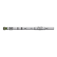
Fishing diagram illustrating component measurements and torque zones for 475 Orbit.
Fishing diagram detailing component measurements and torque zones for 675 Orbit.
Fishing diagram illustrating component measurements and torque zones for 475 X6.
Fishing diagram detailing component measurements and torque zones for 675 X6.
Fishing diagram for 825 PowerDrive X6, showing component measurements and torque zones.
Fishing diagram for 900 PowerDrive X6, detailing component measurements and torque zones.
Fishing diagram for 1100 PowerDrive X6, showing component measurements and torque zones.
| Brand | Extreme Networks |
|---|---|
| Model | PowerDrive Orbit |
| Category | Industrial Equipment |
| Language | English |