EasyManua.ls Logo

Extreme Networks PowerDrive Orbit - 1.3 MAGNETIC MATERIAL REMOVAL; 1.4 TOOL SPECIFICATIONS

Extreme Networks PowerDrive Orbit
35 pages
To Next Page IconTo Next Page
To Previous Page IconTo Previous Page
Loading...
PowerDrive Orbit & X6
Quick Operations Guide - rev1.4
Extreme Equipment Rentals
Page 5 of 35
1.2.3 Flow Restrictor Use and Availability
If the desired pad pressure cannot be achieved by nozzling the bit alone, a flow restrictor can be used.
A PowerDrive Flow Restrictor provides additional pressure drop at the RSS tool to increase pad
pressure and force without affecting the bit TFA. PD
2
includes the ability to suggest a flow restrictor
size to achieve a desired pad pressure. Be sure to verify the suggested size is available in the standard
restrictor kit list below.
475 Restrictors (x/32“) - 8, 9, 10, 11, 12, 13, 14, 15, 16, 18, 20, 22, & 24
675 Restrictors (x/32“) - 16, 18, 20, 22, 24, 26, 28, 30, & 32
900 Restrictors (x/32“) - 26, 28, 30, 32, 34, 36, & 38
1.3 Magnetic Material Removal
Magnetic material present in the mud is highly detrimental to the performance of the PowerDrive control
unit. Magnetic material passing through the torquers causes excessive friction and can lead to toolface
stability issues or complete torquer jamming. To mitigate magnetic material related issues, it is
mandatory to run ditch magnets in the circulating system and clean them at least twice daily.
Ditch magnets should be installed in the flow line, header tanks, and/or possum belly of the shale shakers.
Ditch magnets should be installed and cleaned prior to picking up PowerDrive to ensure the tool is
introduced to a clean system. When adding pre-mixed mud from an outside source, efforts should be
made to run that mud across the magnets prior to pumping it downhole for the first time.
1.4 Tool Specifications
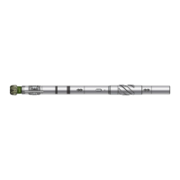
Specifications
PowerDrive Orbit
475 X6
675 X6
825 X6
900 X6
1100 X6
475 Orbit
675 Orbit
Mechanical
Nominal OD, in
4 3/4
6 3/4
8 1/4
9
11
4 3/4
6 3/4
Overall Length, ft
13.65
13.47
13.84
13.84
15.22
13.5
53
Hole Sizes, in
6 - 6 3/4
7 7/8,
9 7/8
10 5/8
11 5/8
12 ¼
18 1/2
20 - 28
6, 6 1/8,
6 ¼, 6 3/4
8 1/2,
8 ¾, 9 7/8”
Bit Speed, rpm
0 - 350
Max WOB, lbf
31,000
180,000
270,000
370,000
225,000
31,000
180,000
Max Torque on Bit, ft.lbf
9,000
18,500
45,000
45,000
70,000
9,000
18,500
Max Overpull, lbf
340,.000
1,100,000
1,100,000
1,800,000
2,500,000
340,000
1,100,000
Pass Through DLS (Sliding)
30
16
12
10
4
30
16
Bit Connection
3 1/2 Reg
4 1/2 Reg
or
6 5/8 Reg
6 5/8 Reg
6 5/8 Reg
or
7 5/8 Reg
7 5/8 Reg
3 1/2 Reg
4 1/2 Reg
Hydraulics
Flow Range, gal/min
1
120 - 310
210 - 970
280 - 2,000
280 - 2,000
280 - 2,000
170-310
210-970
Max Sand Content, %
1
Max Low Gravity Solids, %
8
Max LCM Material, ppb
2
35
50
50
50
50
35
50
Acidity, pH
9.5 - 12
Oxygen, ppm
1
Pressure &
Temperature
Max Temp, F
302
Max Pressure, psi
20,000
Measurements
Inclination Offset to Tool
Bottom, ft
6.76
7.13
7.60
7.70
9.00
6.93
7.19
Azimuth Offset to Tool
Bottom, ft
8.86
9.33
9.80
9.90
11.20
9.03
9.39
Gamma Ray Measurements
Average & 8 or 4-Bin API
Gamma Ray Range, cps
0 - 1,000
Shock Range, g
n
0 - 625
Shock & Vibration Axis
Triaxial
Automation
Automated Loop
Inclination & Azimuth
Downlinking Method
Flow & RPM
Specification Notes:
1. The Operating Envelop is heavily dependent on mud weight. Heavier mud allows for a lower
minimum flow rate. Be sure to consult the tool-specific paperwork to acquire the critical flow rates
for each tool.
2. Fibrous LCM such as cotton seed hulls and cedar fiber should be avoided entirely to prevent filter
plugging and flow kit jamming.