IPCP Pro Series • Hardware Features and Installation 15
Bidirectional Control and Communication Connections and Features
D
3-pole COM ports, RS-232 only and
E
5-pole COM ports, RS-232/RS-422/RS-485 —
Use COM ports for serial control of a display or other device and to receive status
messages from the connected devices. These ports can send
commands from a driver file. RS-232 is the default serial mode
for the 5-pole ports and the only mode for the
3-pole ports.
IPCPProSeries serial protocol:
• 300 to 115200 baud (9600 baud = default)
• 8 (default) or 7 data bits
• 1 (default) or 2 stop bits
• No parity (default), even, odd, mark, or space
parity
• Flow control support (default = none):
• 3-pole ports: software-only (XON, XOFF)
• 5-pole ports: hardware and software
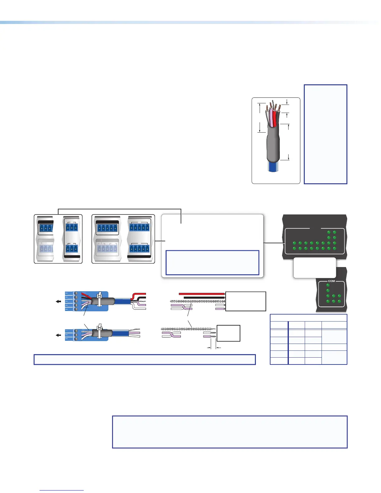
Use the following diagram as a wiring guide to cable the IPCP to other devices.
GTx Rx
COM 2
Tx Rx GTxRxG
RTS
Tx Rx GTxRxG
RTSCTS
CTS
COM 1
GTx Rx
RTSCTS
R
E
IAL
1 7
8
4
Tx
Rx
Tx
Rx
RTS
CTS
COM
12345678
COM
231
Rx
CTS
RTS
Tx
NOTE: If you use cable that has a drain wire, tie the drain wire to ground at both ends.
Strip wires 3/16"
(5 mm) max.
Transmit (Tx)
Receive (Rx)
Transmit
Receive
Transmit (Tx)
Receive (Rx)
Ground
Projector, Panel
Display, PC, or Other
RS-232, RS-422, or
RS-485 Device
RS-232-
Controllable
Device
Request to send
Clear to send
Transmit
Rx Receive
Tx
CTS
RTS
G Ground
Rx
G
Tx
Front Panels
5-pole COM
(RS-232, RS-422, RS-485)
3-pole COM
(RS-232)
Select protocol via software.
COM port default protocol:
• 9600 baud
• 8 data bits • 1 stop bit
• no parity • no ow control
NOTE: The 5-pole COM ports support both
hardware and software ow control.
The 3-pole COM ports support software
ow control only.
Serial (COM) Ports
Heat Shrink
Heat Shrink
Over Shield Wires
To 3-pole
COM port
To 5-pole
COM port
RTS =
Request to Send
CTS = Clear to Send
Tx = Transmitting Data
Rx = Receiving Data
Panels
or or
RS-232
Tx
Rx
Ground
RTS
CTS
RS-422
Tx-
Rx-
Ground
Tx+
Rx+
RS-485
Ground
5-pole COM Pin Configurations
Data-
(pins 1 & 2
tied together)
Data+
(pins 4 & 5
tied together)
Pin
1 (Tx)
2 (Rx)
3 (G)
4 (RTS)
5 (CTS)
Figure 11. Wiring COM ports for Serial Control
For bidirectional serial communication, the transmit, ground, and receive pins must be
wired at both the IPCPProSeries and the other device. Each projector or other device
may require different wiring. For details, see the manual for that equipment or read the
Extron device driver communication sheet, which is included with the drivers.
NOTE: Maximum distances between the IPCP and the device being controlled are
generally up to 200 feet (61 m) but may vary based on factors such as cable
gauge, baud rates, environment, and output levels (from the IPCP and the device
being controlled).
3/16"
(5 mm)
Max.
7/8"
(22 mm)
Heat
Shrink
on Outer
Jacket to
Inner
Conductor
Transition
Extron
Comm-Link Cable
TIP:
Comm-Link
(CTL and CTLP)
cable, shown
at left, is
recommended
for these
connections. For
best results and
to avoid short
circuits, use
shielded wires or
wires insulated
using heat
shrink (instead
of bare wires) for
the common/
drain wires.