Page|10
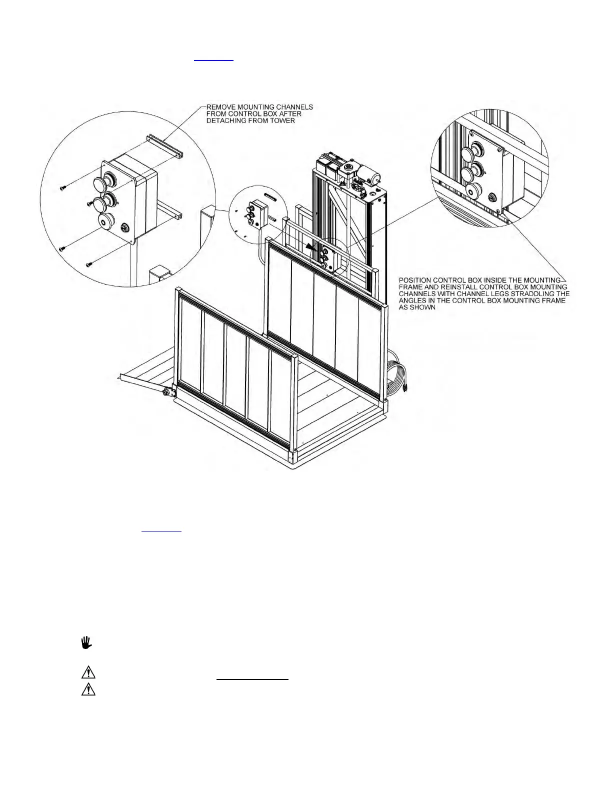
10. Install control box mounting frame to rear guard wall by first removing nuts and bolts from control box
mounting frame posts (FIG. 4.8
).
a. Install the mounting frame between the guard wall and tower with the nuts and bolts oriented as
shown and tightened securely.
FIG. 4.8
11. The control box is secured to inside of tower with zip ties. Locate and cut the zip ties to free the
control box (FIG. 4.8
).
a. Remove fasteners securing mounting channels to control box.
b. Position control box into the mounting frame as shown and reinstall the mounting channels
using the fasteners removed in the previous step.
c. Check to make sure that the control box is free to slide entire length of mounting frame.
CONFIRM BASIC VPL OPERATION
1. The batteries are fully charged when VPL is shipped.
The batteries will maintain their charge for approximately two months under normal conditions.
2. The VPL can now be operated to confirm basic function.
Do not operate the VPL while occupied
until it is anchored in place.
Since the cover panels have not been reinstalled, the lift mechanism will still be exposed at this
point. Be sure to keep all body parts and loose clothing, as well as other people and pets, clear of
the VPL to avoid potential injury.
3. Slide control box to one side so the VPL can be operated while standing on the ground.
 Loading...