15
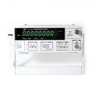
GATE INDICATOR : The gate light, when lit, indicates the main gate is open
and measurement in progress.
DISPLAY : 9 digit(O.56") green LED display used for all read
readings.
NOTE: LAST MEASUREMENT DISPLAY WILL REMAIN FOR 10 SECONDS AFTER
SIGNAL OFF.
UNIT INDICATOR : When lit, indicates that the frequency displayed is in KHz
or MHz, and period is in n, u or mSec.
HOLD INDICATOR : When lit, engaged the hold function.
HOLD SWITCH : In hold function the display held but the counters
continue to increment. When the hold is released, the
display is updated and resumes counting.
RS-232C INDICATOR : TX(transmitting), RX(receiving) blinking(OPTION)
INPUT A, BNC : Input for frequency measurements below 100MHz.
Female BNC connector terminated in 1 M
Ω
input
resistance, Shunted by < 40pF capacitance.
INPUT C, BNC : Input for frequency measurements above 80MHz female
BNC connector terminated in 50
Ω
.
COUPLE. SWITCH : The switch is used to select the input-coupling mode AC
or DC.
ATT. SWITCH : When this switch is set to x 10 (pushed in) the input B is
attenuated 10 :1 before application to the counter with
the switch set to x 1 (pushed out), the input B signal is
applied. The attenuator has no effect on the input C.
LOW PASS FILTER : With this switch pushed in, the input B is routed through
a SWITCH(LPF) low-pass filter with-3dB point of
approximately 100KHz. When it is released, the input B
signal is applied to the counter. Same as input B
function for input A.
OVER FLOW INDICATOR : OF is displayed when overflow.
TILT STAND : Pull out to adjust Tilt.
GATE TIME SWITCH : This switch select the degree of resolution of the display
in all modes except TOTAL.
FUNCTION SWITCH : Select the desired operating mode.
a.FREQ. A. : When this mode is selected, the counter reads the frequencyof
the input A. Resolution is selected using the GATE TIME.
b. FREQ. C
<FC-3000,7150 >
: When this mode is selected, the counter reads the
frequency of the input C.All readings are in MHz.
c. PERIOD A. : When this mode is selected, the counter read the period of the
Test Equipment Depot - 800.517.8431 - 99 Washington Street Melrose, MA 02176
FAX 781.665.0780 - TestEquipmentDepot.com
 Loading...