Page E-3
Repair and Service Manual
B
B
FRONT SUSPENSION AND STEERING
Read all of Section B and this section before attempting any procedure. Pay particular attention to Notices, Cautions, Warnings and Dangers.
Wheel Bearing Packing
Tool List Qty.
Grease Gun................................................................. 1
Bearing Packer (Recommended) ................................ 1
Remove hub from spindle and disassemble. See “Wheel
Bearing and Race Replacement” on page E- 8.
Clean all bearings, grease seal, hub and dust cap in
solvent and dry thoroughly. Inspect for signs of damage.
Pitting or a blue coloration of the rollers will require
replacement of the bearing. If the roller portion of the
bearing is to be replaced, the race must also be
replaced. See “Wheel Bearing and Race Replacement”
on page E-8.
The front wheel bearings are tapered roller type and
must be packed with grease at installation or any time
the bearing is removed for inspection. It is recom-
mended that a bearing packer attached to a grease gun
be used; however, manual packing is acceptable if done
correctly. To pack a bearing manually requires that a dab
of grease be placed in the palm of the hand and the
bearing be dipped in the grease. Force the grease up
through and around all of the rollers until the entire bear-
ing is saturated in grease.
Assemble hub and install on spindle. See “Hub Replace-
ment” on page E - 8.
Once hub is placed onto spindle and before outer wheel bear-
ing is installed, fill the area between the inner and outer wheel
bearings about 1/2 - 3/4 full with grease.
Wheel Bearing Adjustment
Tool List Qty.
Socket, 1 1/2” .............................................................. 1
Ratchet ........................................................................ 1
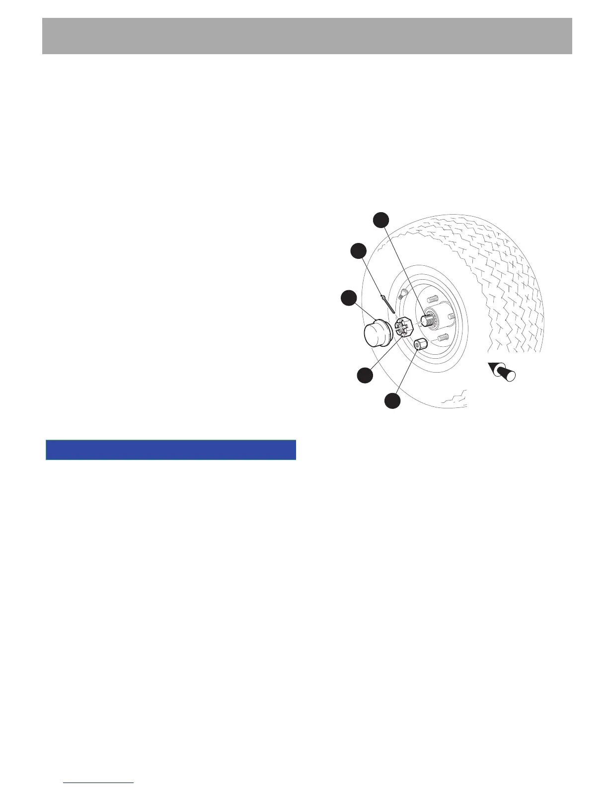
If performing a wheel bearing adjustment only, lift and
support front of vehicle per SAFETY section. Remove
dust cap (1) and cotter pin (2) and loosen castellated nut
(3).
If performing a wheel bearing adjustment as part of
another procedure, make sure wheel is mounted to hub
hand tight with lug nuts (4) and hub is loosely retained
on spindle (5) with castellated nut (Ref Fig. 3).
Seat bearings by rotating wheel while tightening castel-
lated nut until slight resistance is felt.
Rotate the wheel 2 - 3 more turns to displace excess
grease. If required, tighten castellated nut (3) again until
slight resistance is felt. If the cotter pin hole in the spin-
dle (5) aligns with a slot in the castellated nut, insert a
new cotter pin (2). If the hole does not align, the castel-
lated nut must be loosened to align with the closest
available slot in the nut.
Check for smooth and free rotation of the wheel and an
absence of play when the wheel is grasped by the out-
side of the tire. Bend the cotter pin (2) against the flats of
the castellated nut (3).
Replace the dust cap (1) and lower vehicle per SAFETY
section.
Fig. 3 Bearing Adjustment
If completing a wheel bearing adjustment as part of
another procedure, tighten front wheels per WHEELS
AND TIRES section.
Wheel Alignment
Tool List Qty.
Tape Measure..............................................................1
Chalk ...........................................................................1
Wrench, 9/16" ..............................................................1
Wrench, 3/4" ................................................................1
Crowfoot Socket, 3/4” ..................................................1
Torque Wrench, ft. lbs..................................................1
Socket, 13 mm,............................................................1
Ratchet ........................................................................1
Torque Wrench, in. lbs.................................................1
Lift the front of the vehicle and support on jack stands
per SAFETY section. Confirm the alignment of the front
springs. See “Front Spring Replacement” on page E - 7.
Rotate each wheel and scribe a chalk line around the
circumference of the tire at the center of the tread pat-
tern. Lower vehicle and, with tires in the straight ahead
position, roll it forward approximately five feet in order to
allow the tires to take their normal running position.
 Loading...