Page F-5
Repair and Service Manual
B
B
ELECTRONIC SPEED CONTROL
Read all of Section B and this section before attempting any procedure. Pay particular attention to Notices, Cautions, Warnings and Dangers.
Before any electrical service is performed on TCT model
vehicles, the Run-Tow/Maintenance switch must be
placed in the ‘Tow/Maintenance’ position.
If a power wire (battery, motor or controller) is discon-
nected for any reason on the TCT model vehicle, the
Run-Tow/Maintenance switch must be left in the ‘Tow/
Maintenance’ position for at least 30 seconds after the
circuit is restored.
Turn the key switch to ‘OFF’ and place the direction
selector in neutral before disconnecting power by
removing the BL- connection to the battery. Always use
insulated wrenches when working on batteries. To
check for continuity, set the DVOM to the KW setting
and select ‘Continuity’. The meter will give an audible
signal when it detects continuity. If the meter does not
have a continuity setting, set it to KW, the meter will indi-
cate “0” when it detects continuity.
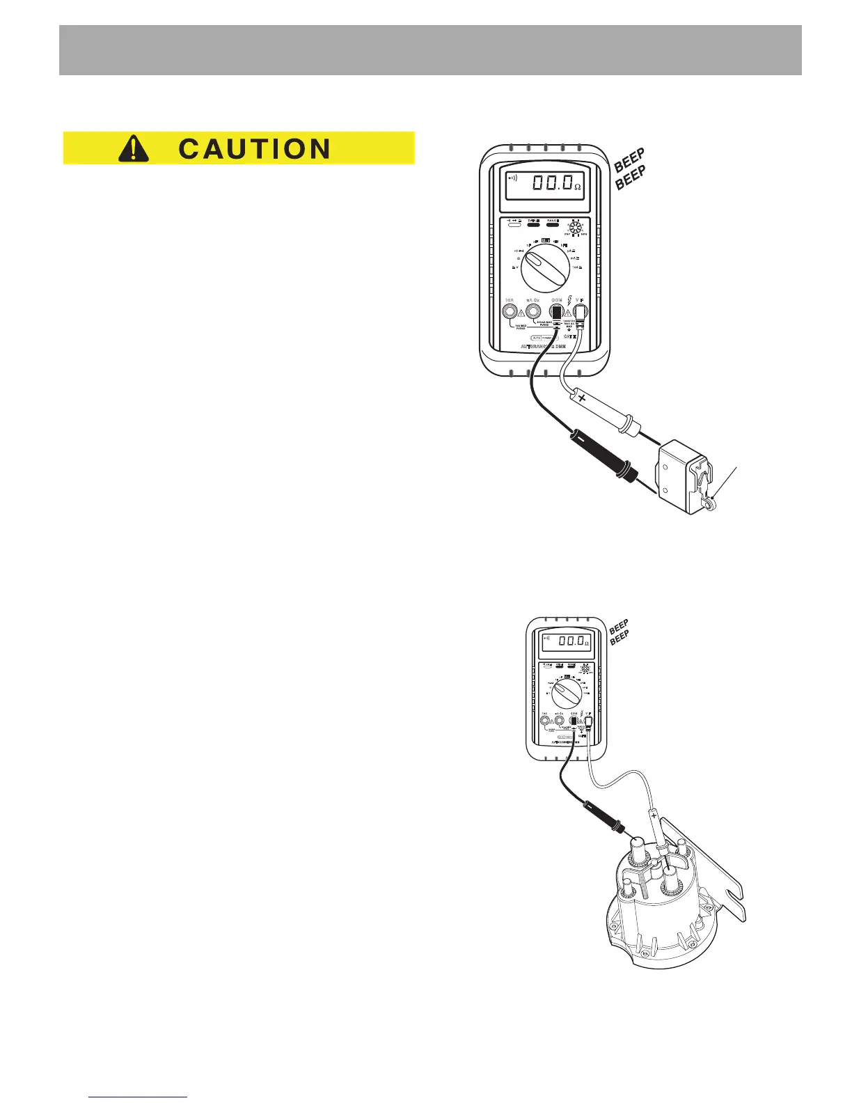
Testing a Switch for Continuity
Place one probe on one contact of the switch, place the
second probe on the second terminal of the switch (Ref
Fig. 5).
Actuating a normally open (NO) switch will cause the
DVOM to show “0” or give an audible indication when
the switch is operated. A normally closed (NC) switch
will cause the meter to show “0” or give an audible indi-
cation when the probes are attached without activating
switch. The audible indicator will stop and the meter dis-
play will indicate a value greater than “0” when the
switch is activated.
The change in display or audible indicator demonstrates
that the switch is functioning.
Testing a Solenoid for Continuity
Place one probe on one of the large terminals and the
other probe on the second large terminal (Ref Fig. 6). If
the meter shows “0” or gives an audible indication, the
solenoid terminals are “welded” closed and the sole-
noid must be replaced.
Fig. 5 Continuity Check of Switch
If the continuity test indicates that contacts are not
“welded” and the wiring to the solenoid coil is good, the
coil has failed and the solenoid must be replaced.
Fig. 6 Continuity Check of Solenoid

 Loading...