Page E-16
Repair and Service Manual
B
FRONT SUSPENSION AND STEERING
Read all of Section B and this section before attempting any procedure. Pay particular attention to Notices, Cautions, Warnings and Dangers.
turned fully to the right forcing passenger spindle arm
against front axle.
Set proper rack extension-to-rack and pinion unit clear-
ance. See “Spindle Contact with Front Axle” on page E -
16.
Install front wheels per WHEELS AND TIRES section
and lower vehicle per SAFETY section.
Check front wheel alignment and adjust if necessary.
See “Wheel Alignment” on page E - 3.
Checking/Adjusting Rack Extension-to-Rack
and Pinion Unit Clearance
Tool List Qty.
Wrench, 11/16” ............................................................ 1
Wrench, 3/4" ................................................................ 1
Wrench, 1/2" ................................................................ 1
Wire Cutter .................................................................. 1
Washer, 1/8” Thick....................................................... 1
Crowfoot Socket, 3/4” .................................................. 1
Torque Wrench, ft. lbs..................................................1
Wire Tie, 10" long ........................................................ 1
Check for proper rack extension-to-rack and pinion unit
clearance by first turning steering wheel fully to the right.
The rear spindle arm on the passenger side must rest
against the front axle (Ref Fig. 20). If it does not, all
adjustment is made at the rack ball joint (6) (Ref Fig.
19). Loosen jam nut (5) at rack ball joint and use wrench
to thread shaft of rack extension (7) further into rack bal-
ljoint. This will provide more travel for the steering wheel
to be turned to the right.
Fig. 20 Spindle Contact with Front Axle
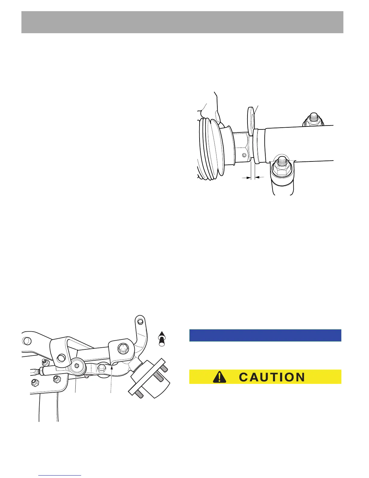
With spindle arm resting against front axle, cut wire tie
(14) securing bellows (9) to rack and pinion unit (1) and
slide bellows away from rack and pinion unit to see large
hex of rack extension. An 1/8” gap should exist between
the large hex and the end of the rack and pinion unit.
Fig. 21 Checking Gap
Adjust, using an 1/8” thick washer as a gauge, by turning
shaft of rack extension with wrench to create the 1/8”
gap. Tighten jam nut (5) to 35 - 45 ft. lbs. (47 - 61 Nm)
torque. Secure bellows to rack and pinion unit with new
wire tie (14).
Steering Wheel Replacement
Tool List Qty.
Socket, 15/16”..............................................................1
Ratchet, 1/2" drive .......................................................1
Plastic Faced Hammer ................................................1
Ball Peen Hammer.......................................................1
Anti-seize Compound ..................................................1
Torque Wrench, ft. lbs. .................................................1
To maintain correct orientation when replacing steering wheel,
first turn wheels straight ahead.
To prevent damage to the steering wheel cover, perform
the following removal procedure. Do not use a screw-
driver to push or pry the retaining tabs.
From the front side of the steering wheel (1), remove the
steering wheel cover (2) by first pulling straight up on the
bottom of the steering wheel cover to release the two
Passenger Side
Spindle Arm
Resting Against
Front Axle
Rack
Ball
Joint
Front
of Vehicle
Gap
Approximately
1/8" Thick Washer
 Loading...