Page F-3
Repair and Service Manual
B
B
ELECTRONIC SPEED CONTROL
Read all of Section B and this section before attempting any procedure. Pay particular attention to Notices, Cautions, Warnings and Dangers.
Run-Tow/Maintenance switch located under the passen-
ger seat.
The Electronic Speed Control system consists of three
separate units; a pedal box, speed sensor, and control-
ler.
Pedal Box
The pedal box assembly is a modularized unit that con-
tains the accelerator pedal, return spring and an
enclosed box that contains the pedal position micro
switch and a solid state Inductive Throttle Sensor (ITS)
that is activated by a moving plunger attached to the
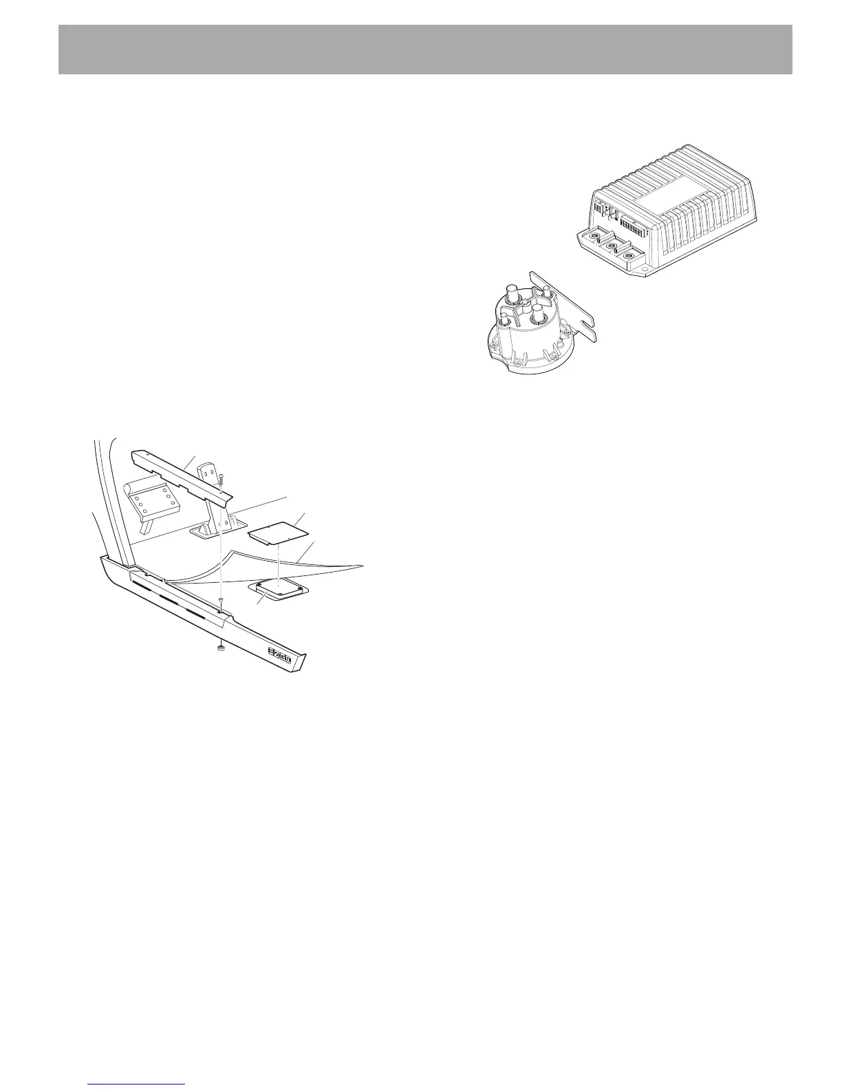
accelerator pedal. To access the pedal box, remove the
rocker panel, lift the floor mat, and remove the access
cover from the floor (Ref Fig. 3). The ITS and plunger
are accessed by removing the two screws and top cover
from the enclosed pedal box.
Fig. 2 Access to Pedal Box
Speed Sensor
The speed sensor uses a sealed sensor to read the
impulses of a ring magnet attached to the armature shaft
of the motor. Magnetic pulses are converted into electri-
cal signals which the controller uses to determine the
motor speed.
Controller
The controller is a solid state unit that activates a sole-
noid and controls the function of the vehicle by respond-
ing to inputs from the ITS, motor speed sensor and
many other units. The controller and solenoid are
located under the seat on the passenger side of the
vehicle (Ref Fig. 3).
Fig. 3 Controller and Solenoid
The main wire harness, pedal box, and speed sensor
are connected to the controller through a 16 pin plug
(Ref Fig. 8). The pedal box is connected to the controller
through a four pin plug on main wire harness. The speed
sensor is connected to the controller through a three pin
plug on main wire harness.
The controller is wired to the batteries and develops a
regulated power supply for the ITS. The plunger position
relative to the ITS varies the voltage which is fed back to
the controller which interprets the change in voltage and
supplies the appropriate power to the motor.
The ITS unit and the controller are both solid state units
that contain no user serviceable parts. The testing pro-
cedures are designed to test the basic functionality
of the power and control wiring systems. Once the
functionality of the wiring has been confirmed, the
remaining tests are used to identify which of the compo-
nents (controller or ITS) must be replaced.
Rocker Panel
Floor Mat
Access Cover
Pedal Box
P
A
R
K
 Loading...