Page 19
May, 2006
415 L LS Operator And
455 D Control Panel Installation Manual
NO = Normally Open, NC = Normally Closed, C = Common, TX = Transmitter, RX = Receiver
Figure 19. Common Accessories wired to 455 D Control Panel
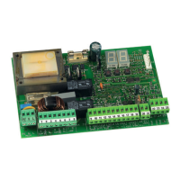
THE 455 D CONTROL PANEL INSTALLATION INSTRUCTIONS
Magnetic Lock
Shadow Loop
Rev ersing Photocells
(for closing)
3 & 4 Wire Radio Receiv ers
N.C.
N.O.
COM
N.C.
N.O.
COM
17
14
18
21
12 vac
Relay
+
-
Lock
12
19
NC
C
Coil Voltage =
Motor Voltage
Additional
Reversing Devices
17
14
9 NO
C
-
+
14
If 4 Wire Receiver
Free Exit Loop/ Phone/ Firebox
(Hold Open Dev ices)
14
9
C
NO
1
2
1
2
3
4
5
19
17
12
19
17
Additional
Reversing Devices
TX
RX
1
2
3
4
5
RX
19
17
12
14
17
TX
+
COM
N.C.
-
LOOP
DETECTOR
Safety Series
Wiring
FAAC
PHOTO-BEAMS
FAAC
1
2
19
8
7
Photocells
(for opening)
FAAC
1
2
1
2
3
4
5
17
19
Additional
Reversing Devices
TX
RX
13
12
14
17
This Jumper Must Be Added
22
23
24
25
16
Wiring The 415 L LS
Limit Switches
FCA
COM
FCC
415 L LS
Motor 1
(Master)
FCA
COM
FCC
415 L LS
Motor 2
(Slave)