13
ENGLISH
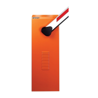
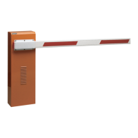
AUTOMATION SYSTEMS 620 - 640 - 642 & 624 MPS
The automation system consists of a white aluminium
beam with red reflectors and of a cataphoresis treated
steel housing with polyester finish.
The housing contains the operator, which consists of a
hydraulic power unit and two pistons. The latter actuate
the rotation of the beam by means of a rocker arm.
A spring mounted on one of the pistons balances the
beam. The housing also contains the electronic control
unit, which is fitted in a watertight container.
The system has an adjustable anti-crushing safety system,
a device that stops and locks the beam in any position,
and a convenient manual release device to be used in
the event of a power failure or malfunction.
Automation systems 620, 640 and 642 & 624 MPS have
been designed and manufactured to control the access of
vehicles. No other use is allowed.
10
1
2
3
4
5
6
7
8
9
11
12
13
14
15
16
17
18
19
20
21
22
23
24
26
25
27
28
29
30
31
32
33
34
35
36
37
Fig. 1
1 Beam
2 Left-hand stroke mechanical stop
3 Drive transmission group
4 Right-hand stroke limit adjustable cam
5 Left-hand stroke limit adjustable cam
6 Rocker arm
7 Left-hand limit switch
8 Oil filler cap
9 Breather screw
10 Cooling fins
11 Left-hand piston bleeder screw
12 Left-hand piston
13 Hydraulic power unit
14 Left-hand connecting pipe
15 Red bypass screw
16 Green bypass screw
17 Housing
18 Left-hand cable passage hole
19 Anchor bolt
20 Base plate
21 Right-hand cable passage hole
22 Earth connector fixing screw
23 Cable pipe
24 624 MPS electronic control unit
25 Right-hand connecting pipe
26 Unlocking lever
27 Support position for 460 mm spring
28 Air intake grille
29 Right-hand piston
30 Support position for400 mm spring
31 Balance spring support
32 Balance spring
33 Right-hand piston bleed screw
34 Thermal probe
(620 rapid and 640 only)
35 Right-hand limit switch
36 Balance adjuster nut
37 Right-hand stroke mechanical stop
38
39
40
41
38 Lock
39 Door
40 Air intake grilles
41 Cooling fan
(620 Rapid and 640 only)
Fig. 2
BARRIER MODEL 620/642 620/642 640/642
RAPID STANDARD STANDARD
22
Max. beam length (m) 2.542.54467
335
Max. opening time (s) <2 <3 3,5 4,5 4 5,5 8
(braking excluded)
Angular velocity (r.p.m.) 7.5 5 4.2 3.3 3.7 2.7 1.8
Pump flow rate (l/min) 2 1.5 1 0.75 2 1.5 1
Max. torque (Nm) 90 110 150 200 210 340-370
250
Types of beams Rigid/Skirt/Articulated
Duty cycle 100% 70% 100%
Power supply 230 V~ (+6 -10 %) 50 Hz
Absorbed power (W) 220
Oil type FAAC XD 220
Oil quantity (l) 2
Motor winding thermal cutout 120° C
Anti-crushing system bypass valves fitted as standard
Temperature range -20 to +55 °C
Casing protective treatment cataphoresis
Casing finish RAL 2004 polyester
Housing protection IP 54
Weight (kg) 73 84
Housing dimension WxHxD (mm)
see Figures 4 and 5
Technical characteristic of electric motor
Speed (Rpm) 2,800 1,400
Power (W) 200 200
Current drawn (A) 1 1.2
Power supply 230V~ (+6 -10 %) 50 Hz
1. DESCRIPTION AND TECHNICAL CHARACTERISTICS
Tab. 1 Technical characteristics of barriers