9
ENGLISH
ENGLISH
Power supply 230V 3ph (+6 -10 %) 50Hz
400V 3ph+N (+6 -10 %) 50Hz
Motor max load 1,3 KW
Accessories power supply 24 Vdc
Accessories max load 500 mA
Warninig light power supply 24V~ (5W max)
Temperature range
- 20°C + 55°C
Fuses transformer primary winding
accessories
Quick-fit plugs - for decoding cards or RP receivers -
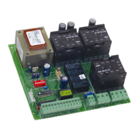
OPEN
Inputs PARTIAL OPEN
STOP
CLOSURE SAFETY DEVICES
LIMIT-SENSORS
warning light
Outputs flashlight
motor
power supply to 24Vdc accessories
pause time (5-10-15-30-60-120-180 sec.)
Programming logics A1/A2/S1/S2/E1/E2/B/C
pre-flashing
Motor braking fixed
Safety timing 255 sec.
F1 Fuse F1 5x20 F5A/250V rapid (transformer)
F2 Fuse F2 5x20 T1,6A/250V delayed (accessories)
SW1 RESET push-button
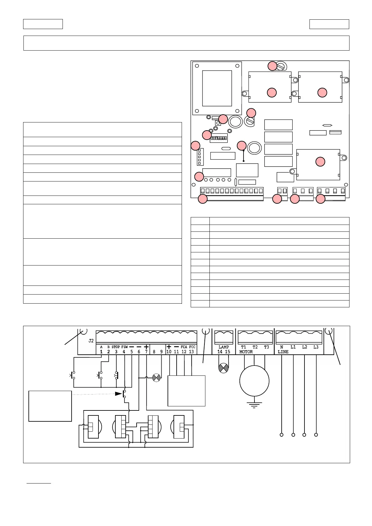
DS1 Programming microswitches
Led Input status signalling LEDs
J1 Quick-fit plug for decoding cards/RP receivers
J2 Low voltage terminal board for inputs/accessories
J3 Flashlight output terminal board (230V~ max 60W)
J4 Motor output terminal board
J5 Line power supply input terminal board
LK1 Bridge for warning light free contact
RL6-7 Motor relay
RL8 Braking relay
TF1
RL7
RL6
RL8
F1
F2
SW1
DS1
J1
J2
J3
J4
J5
A B STOP FSW FCC FCA
LK1
F1
SW1
J1
Led
LK1
J2 J5
RL6
RL8
RL7
J3
J4
DS1
F2
These instructions apply to the following model:
844T Electronic control unit
This appliance can be installed in containers mod. E, L and
LM. Before securing the card in the container, fit the supplied
support feet (long for mod. E, short for models L and LM) in the
3 S-holes (Fig.2).
1. TECHNICAL SPECIFICATIONS
844 T
Fig. 2
Fig. 1
1.1. 844T LAY-OUT
Ü
Before attempting any work on the card (connections,
programming, maintenance), always turn off power.
Warning: If plugs J3 and J4 are disconnected, high voltage
may be present on the flashlight and motor outputs.
TABLE 1 TECHNICAL SPECIFICATIONS OF 844 T CONTROL UNIT
Observe points 10, 11, 12, 13 and14 of the GENERAL SAFETY RULES.
Always separate power cables from control and safety cables
(push-button receiver, photocells, etc.). To prevent any electrical
noise whatever, use separate sheaths.
a
b
Warn.Light
24 Vac
5W max
FAACLAMP
MINILAMP
230 Vac
Altre sicurezze
Other safeties
Autres sécurités
Andere Sicherheiten
Otros disp. seg.
M
3Ph
N
R
ST
OPEN A
OPEN B
STOP
1
2
1
2
3
4
5
1
2
3
4
5
1
2
FINECORSA
LIMIT SWITCH
FIN DE COURSE
ENDSCHALTER
FIN DE CARRERA
400 Vac 3ph + N - 50 Hz
TABLE 2 844T CONTROL UNIT COMPONENTS
2. ELECTRICAL CONNECTIONS WITH 400V 3ph (N.B.: for connection to 230 V 3ph, see Chapter 8)
S
S
S