2
SETTING
+
DL 1
DL 2
DL 3
DL 4
DL 5
J2 4
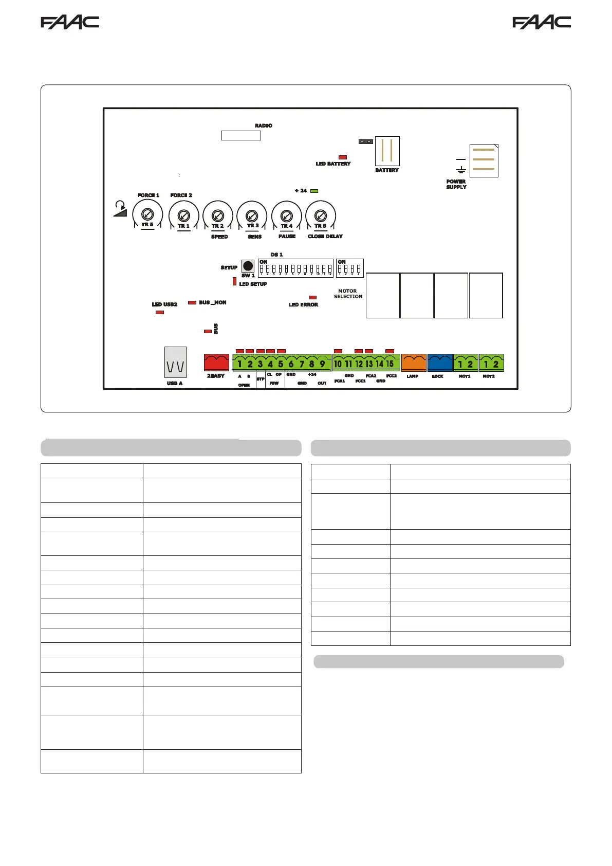
2 LAYOUT AND COMPONENTS
Main power supply
230/115 V~ 50/60 Hz switchable
Secondary power
supply
24 Vdc - 16 A max.
(min. 20 Vdc. - max. 36 Vdc.)
Potenza consumption
stand-by = 4W max. = 400 W
Max load per motor
7 A
Accessory power
supply
24 Vdc - 500 mA
Battery charge current
150 mA
Operating temperature
-4 °F.........+131 °F
Protection fuses
All self-resetting
Main power fuse
2.5 A
Operating Logics
E, A, S, EP, AP, SP, B, C
Operating time
Programmable ( 0 to 10 min)
Pause time
Programmable (0 to 4 min)
Motor force
Programmable with trimmer
Motor speed
Programmable with trimmer
Connector inputs
Power supply, Battery, Radio recei-
ver, USB
Terminal strip inputs Open A, OpenB, Stop, Open safety
fotocell, Closing safety fotocell, Limit
switches
Terminal strip outputs Light, Motors, Lock, One program-
mable Output, accessory power
1 TECHNICAL SPECIFICATIONS
RADIO
Connector for the radio receiver
BATTERY
Connector for the backup battery
J24 Jumper to disable battery charging
(With the jumper ON the battery is char-
ged)
POWER SUPPLY
DC Power supply input
TR1 to TR6
Programming Trimmers
+24 LED
DC power indicator
SW1 - SETUP
Pushbutton for automatic setup
DS1 - DS2
Programming dipswitches
LED ERROR
Troubleshooting indicator
USB A
USB connection for software upgrade
On the radio connector it’s possible to plug in receivers RP
and RP2. With a single channel radio RP it will be possible
to activate only the OPEN A input, with a dual channel radio
RP2 it will be possible to activate both OPEN A and OPEN
B inputs.
Plug in the radio board with the component side towards
the internal part of the board.
Make sure you insert or disconnect the board ONLY with
the power o.
RADIO CONNECTION