MAP2 / MAP2LCLG-SL
FABER-COM srl - Via Romana 36/1 - 42028 Poviglio (RE) - Italy Tel. +39-0522-960428 Fax. +39-0522-969644 - www.fabercom.it
\Prodotti\Limitatore CLG\PCLG-LxE[CLG-SL- Barra LED]\Documenti\SM#Limitatore CLG-SL_v102 - 19/04/2017 Page 2 / 6
FEATURES
Power supply range: from 10Vdc, up to 30Vdc.
Connector FCI, 24 ways, IP68, mechanical polarization, easy locking cam.
Maximum output current supply: 3A
In the respect of EN 954-1 the safety features belongs to category 2
Two differnet working areas with two different load limits.
Fast and easy programming sequence.
HUMAN MACHINE INTERFACE
The green led on the board, in normal operation mode, is lighten to show the power supply.
When faults are present, the green led blinks following a particular sequence related to the fault
reasons. (look at the last page for a detailed blinking sequence meaning).
Leds placed into the emercency button box (red colour and yellow colour), are lighten in the
floowing situation:
- When emercy button is pressed, the red button and the yellow butto blink together.
- When the load exceed the 90% of the limit, yellow led is ON.
- When the load exceed the 100% of the limit, red led is ON.
INPUT
- RESET: That input allow the load limiter to power the valve for a short period, even if the
load value exceed the load limit.
- LIMIT REDUCTION: It is used to set the working area. When it is low value, then the load
limiter compare the pressure from the transducer with a reduced threshould.
- PRESSURE transducer input: 4÷20 mA.
- INPUT DV: It allow to connect the load limiter to a remote control in a safety way.
- DIFFERENT POWER SUPPLY for logic control unit and powered OUTPUT.
OUTPUT
- Powered output to drive bypass valve coil. The board implements a feedback current control
on the mentioned output.
- Two powered output to drive external optional lamps. The mentoned outputs are driven as well
as the leds into emergency button box (90% and 100%).
SETTING PARAMETERS
The load limiter's threshoulds are programmed using an exernal, little, 4 bottons, keyboard. The
keyboard is an optional. His name is "PRG2_CLG". When it is connected the green led blinks
for time in a second.
In order to set whole the load limiter's parameters and download the working configuration, an
optional serial interface can be used to connect the PC to the load limiter. The program interface
is named SepSim.
HARDWARE KEY TO INCREASE THE LOAD LIMIT THRESHOLD
The PRG2_CLG can be used even to increase the load limit thresold up to 125%, for a brief
period of time.
In order to increase the limit: when you connect the PRG2_CLG, the "+" button has to be
pressed within 5 seconds then kept pressed till the green led blinking will becomes slower.
Features
Human machine interface
Power supply range: from 10Vdc, up to 30Vdc.
Connector FCI, 24 ways, IP68, mechanical polarization, easy locking cam.
Maximum output current supply: 3A
According to EN 954-1 Safety Standards: Category 2
Two different working areas with two different load limits.
Fast and easy programming sequence.
The green led on the board, in normal operation mode, is lighten to show the power supply.
When faults are present, the green led blinks following a particular sequence related to the fault reasons. (look at
the last page for a detailed blinking sequence meaning).
Also, it is present a LED bargraph to show the load percentage in real time, compared to the maximum load. When
the load exceedes the 100% of the limit, red LED of the bargraph blinks.
Leds placed into the emergency button box (red colour and yellow colour), are lighted in the following situations:
- When emergency button is pressed, the red and the yellow blink together.
- When the load exceedes the 90% of the limit, yellow led is ON.
- When the load exceedes the 100% of the limit, red led is ON.
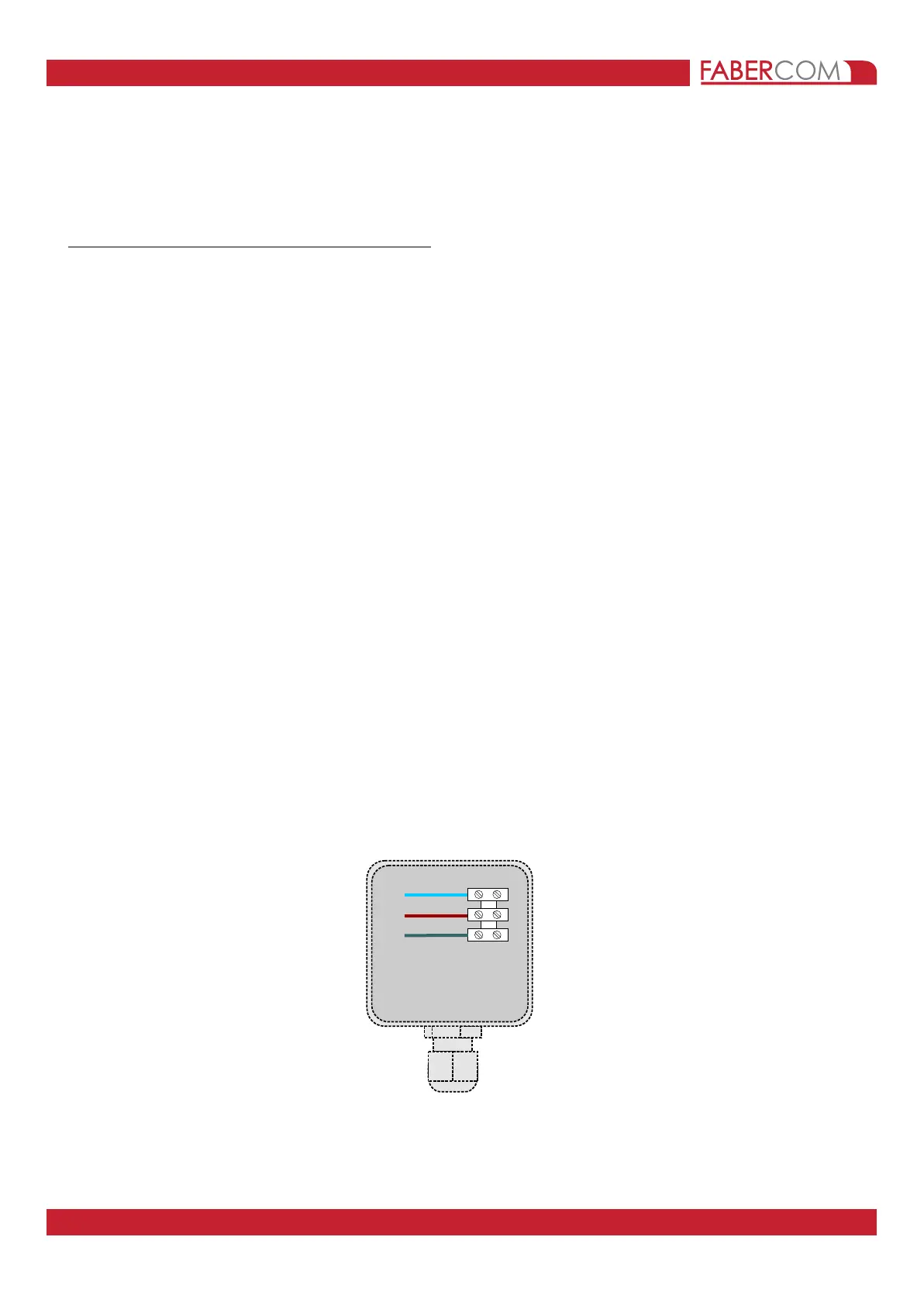
The CLG-SL load limiter is able to control a Bar LED in order to signal when load exceed the 90% and 100% of
maximum permitted load.
For this purpose, it is necessary open the box of secondary emergency push button and connect a cable as
instructed below.
CARATTERISTICHE TECNICHE
Tensione di alimentazione unica da 10Vdc a 30Vdc
Connettore a 24 poli IP68 con aggancio rapido a slitta.
Corrente massima uscite di potenza: 3A
Classificazione sicurezza secondo norme EN954-1: Categoria 2
Interfaccia utente con 1 LED (led mode) per mostrare lo stato di
- Presenza tensione di alimentazione
- Segnalazione allarmi e anomalie (in ultima pagina è presente l'elenco delle segnalazioni)
I led presenti sul cablaggio, posti nella scatola dei funghi di emergenza, svolgono diverse segnalazioni
- Carico al 90% (quando la luce gialla è accesa fissa)
- Carico al 100% (quando la luce rossa è accesa fissa)
- Fungo di emergenza premuto (quando entrambe le luci lampeggiano)
INGRESSI
- RESET (riarmo con temporizzazione opzionale)
- Decremento portata (zona di lavoro)
- Lettura di un trasduttore di pressione a due fili 4÷20 mA con controllo del range di
funzionamento, segnalazione del guasto e blocco delle uscite.
- Predisposizione per l'ingresso DV dell'eventuale radiocomando installato sulla gru.
- Ingresso separato per l'alimentazione delle uscite di potenza (positive) con relè sezionatore
generale controllato in retroazione. A tale ingresso sarà collegato il positivo della serie dei funghi di
emergenza.
USCITE
- Uscita di potenza per il comando elettrovalvola di bypass (controllata in retroazione).
- n° 2 uscite di potenza (negative) per il comando delle lampade esterne di segnalazione del
carico al 90% e al 100%.
PROGRAMMAZIONE DA PARTE DEL COSTRUTTORE
La programmazione delle soglie di intervento è impostabile, in modo veloce e intuitivo, attraverso un
tastierino esterno (opzionale) denominato "PRG2-CLG".
Per mezzo di un adattatore di interfaccia seriale e di un apposito cablaggio di adattamento è possibile
collegare la scheda ad un Personal computer per la configurazione dei parametri di funzionamento più
delicati (ritardo del RESET, variazioni delle soglie associate agli ingressi di incremento e decremento
portata, configurazione di un trasduttore di pressione con scala diversa, ecc, ecc).
PROGRAMMAZIONE DA PARTE DELL'INSTALLATORE
L'installatore ha a disposizione un tastierino differente da quello del costruttore (PRG2-DEC), per il
declassamento della gru. L'installatore può variare le soglie di intervento, ma solo per valori al di sotto di
quelli impostati dal costruttore. Il tastierino permette di richiamare, in caso di necessità, i dati di fabbrica.
CHIAVE HARDWARE DI INCREMENTO DELLA SOGLIA DI INTERVENTO
Il tastierino PRG2 (sia DEC che CLG) permette inoltre di incrementare la soglia di intervento al 125%.
Per attivare questa funzione si deve premere per 5 secondi il tasto "+", entro 5 secondi da quando è
stato collegato il tastierino alla centralina.
Quando si estrae il tastierino, o dopo un'ora dall'inserimento, la soglia di intervento del blocco momento
torna al valore normale di lavoro.
La centralina CLG permette la limitazione del carico di una gru.
Il carico viene misurato mediante un trasduttore di pressione 4÷20 mA sul martinetto del primo braccio.
Quando il limite di sollevamento della gru viene superato la gru viene bloccata spegnendo l'uscita ELV1 che sarebbe, in condizioni normali di lavoro, sempre accesa.
+ (blue)
90% (brown)
100% (grey)
 Loading...