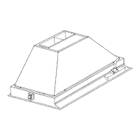
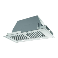
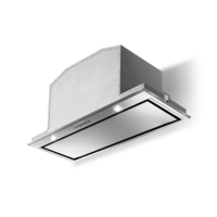
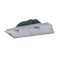
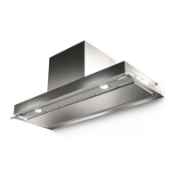
The Faber Inca Pro Plus is a range hood designed for kitchen ventilation, available in several models with varying dimensions and blower configurations. It can be installed in either ducted (vented to the outside) or non-ducted (recirculating) configurations.
Function Description:
The primary function of the Faber Inca Pro Plus range hood is to remove smoke, grease, and odors from the cooking area. It achieves this through a powerful blower system and a series of filters. In ducted installations, the air is exhausted to the outdoors, while in non-ducted (recirculating) installations, the air is filtered through charcoal filters and then returned to the kitchen. The hood features integrated lighting to illuminate the cooking surface.
Important Technical Specifications:
- Electrical Requirements: 120 volt, 60 Hz AC-only electrical supply on a separate 15 amp fused circuit. A time-delay fuse or circuit breaker is recommended. The unit must be connected with copper wire only, conforming to the National Electrical Code, ANSI/NFPA 70, and local codes. Electrical ground is required.
- Clearance: A minimum of 24 inches of clearance is required between the bottom of the range hood and the cooking surface or countertop. For gas cooktops and combination ranges, a minimum of 30 inches is recommended and may be required. Overhead cabinets on both sides of the unit must be a minimum of 18 inches above the cooking surface or countertop.
- Ductwork: Metal ductwork is required for ducted installations. Flexible ductwork is not recommended due to back pressure and air turbulence. Ductwork should terminate outside the home and not vent into walls, ceilings, attics, crawl spaces, or garages. The length and number of elbows in the ductwork should be minimized for efficient performance.
- Blower Options:
- Internal Blowers:
- IB300 (300 cfm)
- IB600 (600 cfm PRO)
- IB1200 (1200 cfm PRO, requiring 2 blowers)
- Remote Blowers (with INLBKIT accessory kit):
- RB900 (900 cfm)
- RB1200 (1200 cfm)
- Generic In-Line/Remote Blowers: Must be rated maximum 4.2 A, suitable for solid-state variable speed control, and used with the INBKLIT accessory kit.
- For 30" Inca models, it is recommended that blowers are kept at a maximum CFM of 600.
- Dimensions (Vary by model):
- 19" Deep Models (A1, A2, A3, A4):
- Widths: 28-1/2" (A1), 34-1/2" (A2), 40-9/16" (A3), 46-9/16" (A4)
- Depths: 29-1/2" (A1), 35-1/2" (A2), 41-9/16" (A3), 47-9/16" (A4)
- Height: 7-15/16" (11" with ducting)
- Top dimensions: 18-11/16" deep, widths vary (21-1/4" to 34-9/16")
- 22" Deep Models (A1, A2):
- Widths: 34-1/2" (A1), 46-9/16" (A2)
- Depths: 35-1/2" (A1), 47-9/16" (A2)
- Height: 7-15/16" (11" with ducting)
- Top dimensions: 18-11/16" deep, widths vary (22-1/2" to 34-9/16")
- Cabinet Opening Dimensions (for installation):
- 19" Deep Models:
- 30" x 19" hood: 28-5/8" (X) x 19-7/8" (Y)
- 36" x 19" hood: 34-3/4" (X) x 19-7/8" (Y)
- 42" x 19" hood: 40-3/4" (X) x 19-7/8" (Y)
- 48" x 19" hood: 46-3/4" (X) x 19-7/8" (Y)
- 22" Deep Models:
- 36" x 22" hood: 34-3/4" (X) x 22-7/8" (Y)
- 48" x 22" hood: 46-3/4" (X) x 22-7/8" (Y)
- Minimum cabinet opening height: 16".
- Lighting: Gu10 self-ballasted LED lamps, listed in accordance with UL 1993/NMX-J-578/1-ANCE/CSA C22.2 No. 1993.
Usage Features:
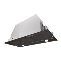
- Control Panel: Located in the center of the hood bottom, featuring a Light On/Off Button (A) and a Blower On/Off Button (B).
- Light Control (A): Position "0" turns lights off; turning the switch to the right turns lights on.
- Blower Control (B): Move the dial to the right to turn the blower ON and vary its speed; turn to the left to "0" to turn it OFF.
- Optimal Performance: Start the range hood several minutes before cooking to establish proper airflow. Allow the unit to operate for several minutes after cooking is complete to clear smoke and odors.
- Range Top Grease Fire Safety:
- Never leave surface units unattended at high settings.
- Always turn the hood ON when cooking at high heat or flambéing food.
- Use proper pan size.
- In case of fire, smother flames with a lid, cookie sheet, or metal tray; turn off the burner. Do not use water. Use an extinguisher only if trained, the fire is small, and the fire department is called.
Maintenance Features:
- Grease Filters: Stainless steel grease filters and grease rail should be cleaned frequently with hot detergent solution or in a dishwasher. Ensure they are completely dry before re-installation. The filters are installed by tightening two knobs with screws, then inserting the filter into the front edge of the hood and securing it above the grease rail at the back.
- Charcoal Filters (for non-ducted recirculation):
- Activated charcoal filters are not washable and cannot be regenerated.
- Should be replaced approximately every 4 months or more frequently with heavy usage.
- To install, attach one charcoal filter to each end of the blower, pressing it tightly against the black grid and rotating clockwise until it locks.
- To remove, rotate counterclockwise until it unlocks from the motor housing and pull off sideways.
- Only conversion kit Model FILTER1 (sku # FILTER1 or FILTER1LL) should be used for recirculation mode to reduce fire and shock risk.
- Exterior Surfaces: Clean with a commercially available stainless steel cleaner. Avoid abrasive cleaners and scouring agents to prevent scratching.
- Lighting Unit: Replace lamps with new ones of the same type, ensuring proper insertion of the two pins into the lamp holder housings.
Installation Process (General Steps):
- Prepare Cabinet Opening: Cut out the opening in the underside of the cabinet according to the specified dimensions for your model. It is recommended that the insert hood is supported by a 3/4" wood base.
- Blower Installation (Varies by kit):
- IB300/IB600: Install Duct Plate B, motor kit, and damper A. Connect wire cable D (6-hole end to wire box, 9-hole end to motor).
- IB1200: Install Duct Plate B, 2 motor kits, and 2 dampers A (or 10" duct transition E). Connect wire cable D (6-hole end to wire box, 9-hole ends to both motors).
- RB900/RB1200 (Remote Blower) or In-Line Blower (INLBKIT): Install Plate B with the second wiring box. Connect the wire from the second wiring box to the 6-hole end of the first wiring box, and the wire from the electronic board to the 9-hole end of the first wiring box. Pass the remote blower cable through the knockout hole and connect it to the second wiring box. Follow instructions included with the remote blower for external installation.
- Side Trim Installation: Remove plastic covering and install the 4 side trim pieces using screws.
- Secure Hood:
- With Side Mount Clips: Install the hood into the cabinet opening, engage the four spring-loaded side mount clips onto the cabinet wood base. Tighten the screws in each clip from underneath. Place plastic stoppers (10).
- Without Side Mount Clips: Secure the hood with six screws (9d) on the front side (Figure 3a). Place six stoppers (10) on the front side (Figure 3b). Alternatively, attach the hood on the short side of the cabinet using screws (purchased separately) and secure it with three screws into wood support/cabinet framing from inside. Place four plastic stoppers (10) from underneath.
- Ductwork Connection: Connect ductwork to the damper and seal all connections with duct tape.
- Electrical Connection: Remove electrical knockout, feed power supply cable, and connect wires (White to White, Black to Black, Green/Yellow ground to green grounding screw). Replace field wiring compartment cover.
- Test: Turn on power supply, blower, and light to ensure proper operation.
Warranty:
Faber products are warranted against defects in materials and workmanship for 1 year from the original purchase date (proof of purchase required). This covers labor and replacement parts. The warranty does not cover installation issues, consumable parts (light bulbs, fuses, filters), non-residential use, damage from misuse or improper installation, units operated outside the US/Canada, unauthorized modifications, or travel/transportation expenses for remote locations.