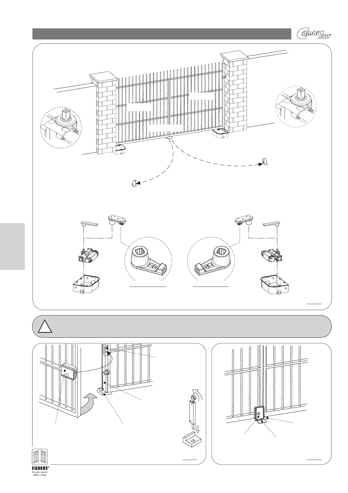
MAIN COMPONENTS FOR STANDARD INSTALLATION
Right gate open stop
(not provided by the manufacturer)
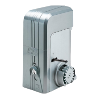
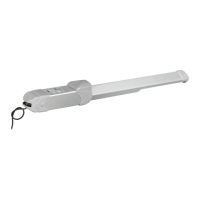
Right Combi 740
Left gate open stop
(not provided by the manufacturer)
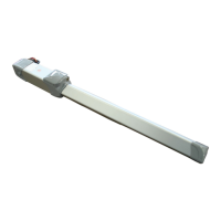
Left Combi 740
Left gate
Right gate
Dx
The abbreviation “Dx”
indicates
the Right Combi 740
(as seen from inside
the property)
The abbreviation “Sx”
indicates
the Left Combi 740
(as seen from inside
the property)
Sx
Gate close stop
Support plate
with ferrule
Left
Combi 740
Left
Normal
enclosure
Manual release
Left
Support plate
with ferrule
Right
Combi 740
Right
Normal
enclosure
Manual release
Right
Electric lock catch plate
to be secured on the first
leaf that closes,
or on the wall with single
leaf gates
Gate close stop bolt
welded on the
first leaf that closes
Gate close stop
to be secured to the ground
“Horizontal” Electric lock
on the second leaf that closes.
For single-leaf gates
this solution is recommended
Gate close
stop
Electric lock catch plate
to be secured to the ground
Vertical
application of the
Electric lock
VIEW FROM BELOW VIEW FROM BELOW
PIC. 4
!
Important: For installations with Combi 740 (Normal or Locking) with leafs longer than 2.0 meters it is always necessary to install an
Electric lock or a Leaf stop bolt: the possible solutions are shown in Pic. 5 and Pic. 6. For a single leaf, it is recommended
that the electric lock be installed horizontally.
PIC. 5 PIC. 6
20
English