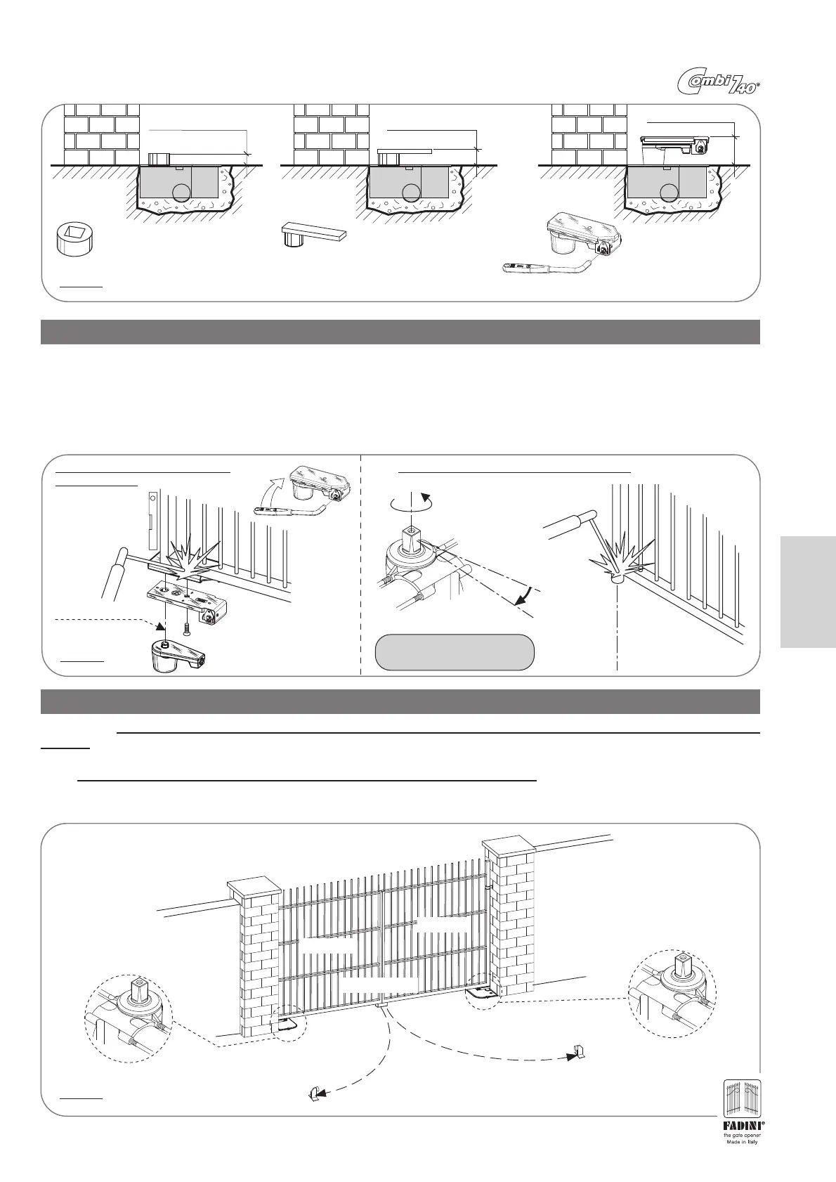
PIC. 13
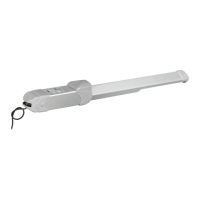
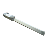
PREPARING THE LEAF: SECURING THE EMERGENCY RELEASE OR THE FERRULE
After having allowed the concrete to set around the Enclosure, and depending on the application requirements for the leaf to be
operated, the following overall measurements will be obtained (Pic. 13):
Measurement A=30mm
code 761 Ferrule with square hole
Measurement A=42mm
code 746 Ferrule with square hole
with Support plate (Right or Left)
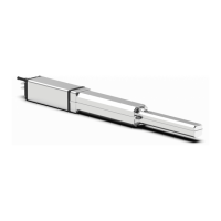
The connection between the gate leaf to be opened and the Combi 740 operator may occur in three possible versions depending on if there is an
emergency manual release system, a simple Support plate with square hole ferrule or only a Square hole ferrule. However, in all cases it is necessary
to tightly weld these three items to the leaf base, in alignment with the upper hinge of the leaf itself (Pic.14).
At this time, the measurement indicated in Pic. 13, between the enclosure and the above leaf becomes important.
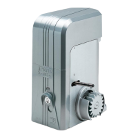
IMPORTANT: the Support plate with a square hole ferrule and the single square hole ferrule must be welded to the leaf with the Combi 740 shaft
rotated by 5° or 10°, before it arrives at the end of travel. (Pic.14). (Putting into phase process).
Measurement A=80mm
code 748 Emergency
release with square ferrule,
release key and welding
plate (Right or Left)
Sx
Emergency Manual Release Gate connection: by welding either the ferrule directly or the support plate
Leaf rotation
axle
Level
Leaf rotation
axle
Travel end axle
Leaf axle
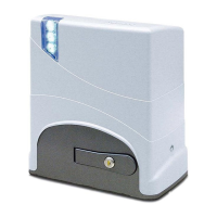
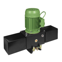
INSTALLING THE RIGHT AND LEFT COMBI 740 INSIDE THE ENCLOSURE
IMPORTANT: The Right and Left Combi 740 are installed respectively to the right and left of the gate, as seen from the inside of the
property: this distinction (version Right and Left) is indicated by the stamp on the base of the square rotation shaft, made during the
manufacturing process at the factory (Pic.15).
NOTE: All what previously described also applies to installations with single leaf swing gates.
IMPORTANT: Before installing and making the electrical connections to the automated devices, the leaf opening and closing stops
must be secured to the ground (Opening leaf stop approx. 5° before the rotation shaft's end of travel).
Sx
Dx
Left gate
Right gate
Right leaf open gate stop
(Not provided by the manufacturer)
Right Combi 740
Left leaf open stop
(Not provided by the manufacturer)
Left Combi 740
The abbreviation “Dx”
indicates the Right Combi 740
The abbreviation “Sx”
indicates the Left Combi 740
Close stop
Shaft rotation
closing
end of travel
Rotate by 5° or 10°, before the rotation
shaft arrives at the end of travel.
PIC. 14
PIC. 15
23
English
IMPORTANT: the single square hole ferrule must be welded to the leaf with the Combi 740 shaft rotated by 5° or 10°, before it arrives
at the end of travel. (Pic.14). (Putting into phase process).
Sx
Welding the manual emergency override
or support bracket
Gate connection: by welding either the ferrule directly
Leaf rotation
axle
Level
Travel end axle
Closed gate axle
PIC. 14
Shaft rotation
closing
end of travel
Leaf rotation
axle
Rotate by 5° or 10°, before the rotation
shaft arrives at the end of travel